Wellhead Hold-Down Apparatus and Method

Inactive Publication Date: 2008-04-24
OIL STATES ENERGY SERVICES +1
View PDF6 Cites 0 Cited by
  • Summary
  • Abstract
  • Description
  • Claims
  • Application Information

AI Technical Summary

Benefits of technology

[0008]The deficiencies of the prior art are also addressed by a method to attach a communications tool lubricator assembly to a wellhead stack. The method preferably includes attaching a hold-down retainer to a component of the wellhead stack, wherein the retainer includes a locking profile. The method also preferably includes mounting the lubricator assembly to a proximal end of a hold-down mandrel, wherein the mandrel includes an engagement profile on an outer surface. The method preferably includes engaging the mandrel into the retainer, wherein the engagement profile is preferably configured to engage the locking profile and retain the mandrel. The method also preferably includes preventing the escape of borehole fluids from the wellhead stack through the use of a sealing mechanism between the mand

Problems solved by technology

Because the drillstring and wellbore are often several thousand feet in depth, a tremendous amount of pressure is required to pump the drilling mud down to the bit and back up to the surface in a complete c

Method used


Image

  • Wellhead Hold-Down Apparatus and Method
  • Wellhead Hold-Down Apparatus and Method
  • Wellhead Hold-Down Apparatus and Method

Examples


Example

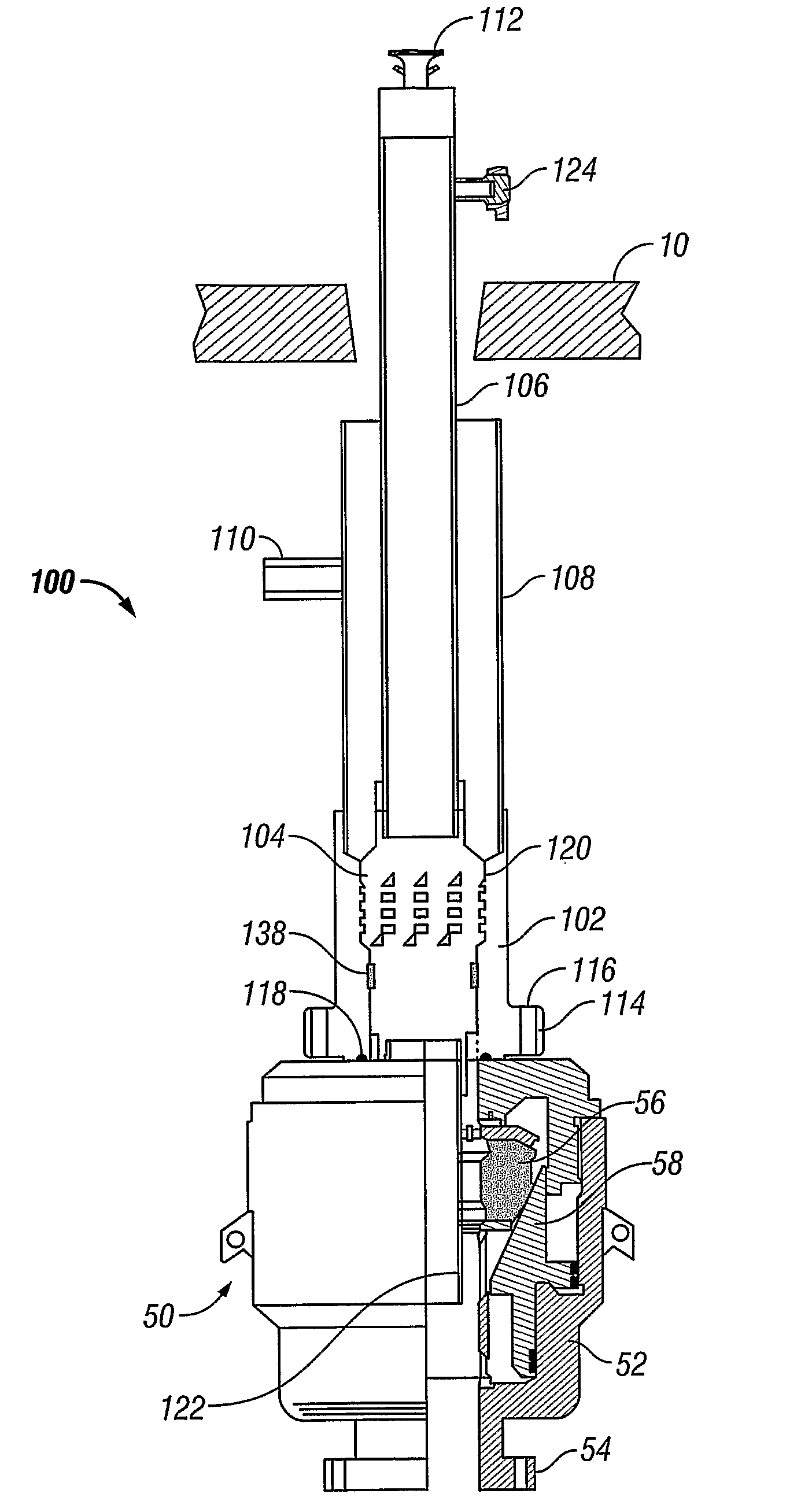
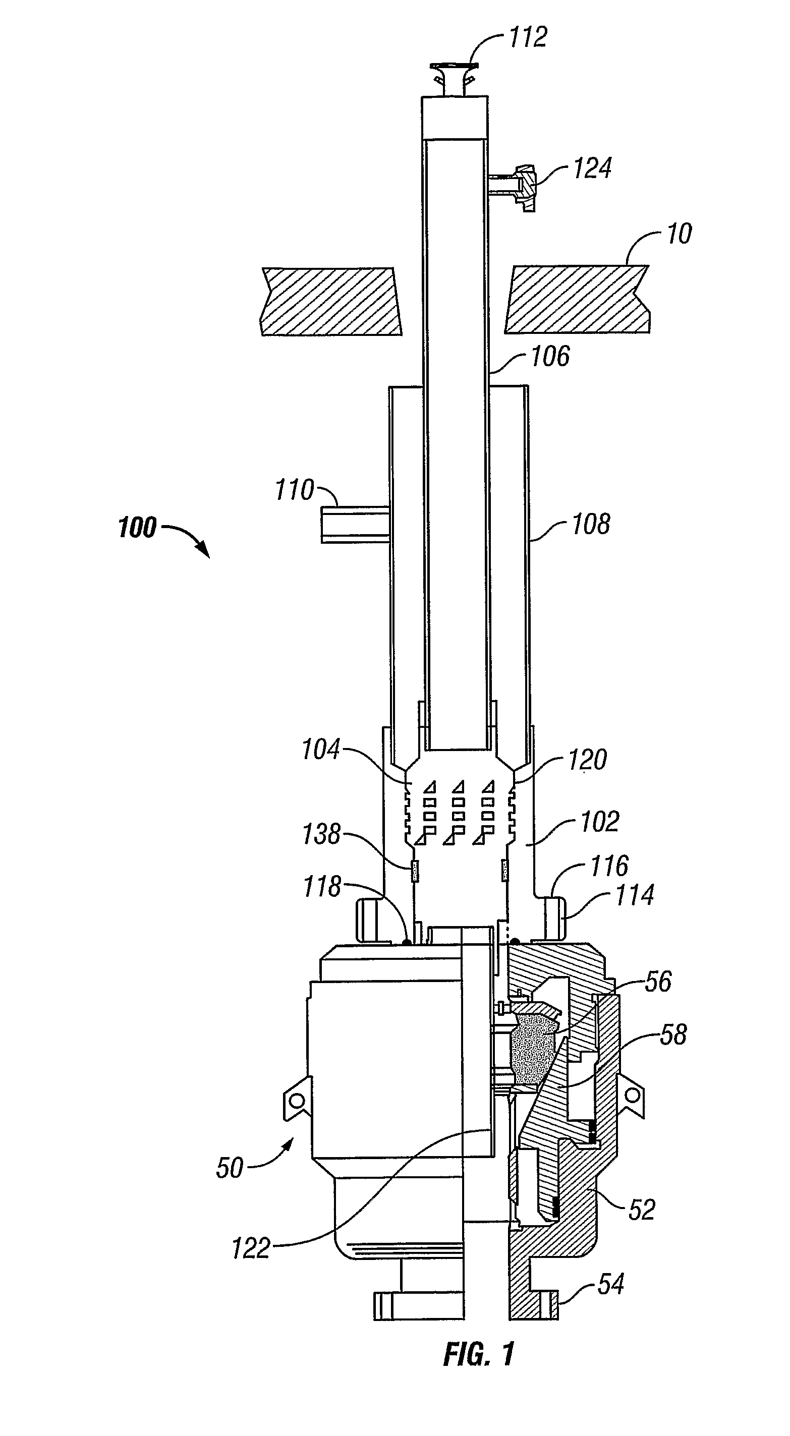
[0015]Referring initially to FIG. 1, a hold-down apparatus 100 in accordance with a preferred embodiment of the present invention is shown below a rig floor 10 mounted atop an annular blow out preventer 50. Annular BOP 50 typically includes a main body 52, a mounting flange 54, a packing element 56, and a compression piston 58. BOP 50 is mounted atop the wellhead or other equipment (not shown) by bolted flange 54. Annular BOP serves to seal off the annulus between a pipe or tubing string engaged therethrough and a borehole in the event of a downhole surge in pressure or “kick.” Hydraulic pressure is maintained in BOP 50 to drive piston 58 into packing element 56 to compress it against anything engaged therethrough. In the event of a sudden increase in pressure, BOP 50 can be configured so that piston 58 compresses packing element 56 even tighter as annular pressure increases such that the escape of annular fluids is prevented.

[0016]Referring still to FIG. 1, the hold-down apparatus ...


PUM


Abstract

An apparatus (100) and method for removably mounting a lubricator assembly (106) to a component of the wellhead stack. The component of the wellhead stack is an annular blowout preventer (BOP) (50). Tool and communication conduit lubrication and access to the wellbore without requiring activation of the packing element of the BOP (50).

Description

BACKGROUND OF THE INVENTION[0001]Well drilling operations are typically performed through a long assembly of threadably connected pipe sections called a drillstring. Often, the drillstring is rotated at the surface by equipment on the rig thereby rotating a drill bit attached to a distal end of the drillstring downhole. Weight, usually by adding heavy collars behind the drill bit, is added to urge the drill bit deeper as it is rotated. Because subterranean drilling generates a lot of heat and cuttings as the formation below is pulverized, drilling fluid, or mud, is pumped down to the bit from the surface.[0002]Typically, drill pipe sections are hollow and threadably engage each other such that the bores of adjacent pipe sections are hydraulically isolated from the “annulus” formed between the outer diameter of the drillstring and the inner diameter of the wellbore (either cased or as-drilled). Drilling mud is then typically delivered to the drill bit through the bore of the drillstr...

Claims


Application Information

Patent Timeline
IPC IPC(8): E21B19/00
CPCE21B33/072
Inventor JONES, BILL D.ROBSON, MARK D.
Owner OIL STATES ENERGY SERVICES
Why Eureka
Try Eureka