Exhaust Hood

Active Publication Date: 2019-11-28
NINGBO FOTILE KITCHEN WARE CO LTD
View PDF0 Cites 5 Cited by
  • Summary
  • Abstract
  • Description
  • Claims
  • Application Information

AI Technical Summary

Benefits of technology

[0012]A plurality of points fitting with a Fibonacci spiral line are arranged on a vertical section along the center of the rotary shaft of the motor, wherein a starting point of the Fibonacci spiral line is arranged on the inner surface of the front plate below the air inlet, a top arc line at the top of the air-intake ring, a bottom arc line at the bottom of the air-intake ring are respectively tangent to a curve with a radius of Fibonacci sequence Fn-1, and an endpoint of the free edge of the smoke deflector coincides with an endpoint of a curve with a radius of Fibonacci sequence Fn. In this way, a smooth smoke suction passage can be formed from the air inlet of the range hood to the air-intake

Problems solved by technology

Although the close-suction range hoods have a lower smoke inlet than other types of range hoods, due to the large distance between the burner of the stove and the wall surface in practical applications, such range hoods are not enough deep to completely cover the stove within the smoke trapping region.
In addition, a large space is needed by the large amount of smoke, which is generat

Method used


Image

  • Exhaust Hood
  • Exhaust Hood
  • Exhaust Hood

Examples


embodiment 1

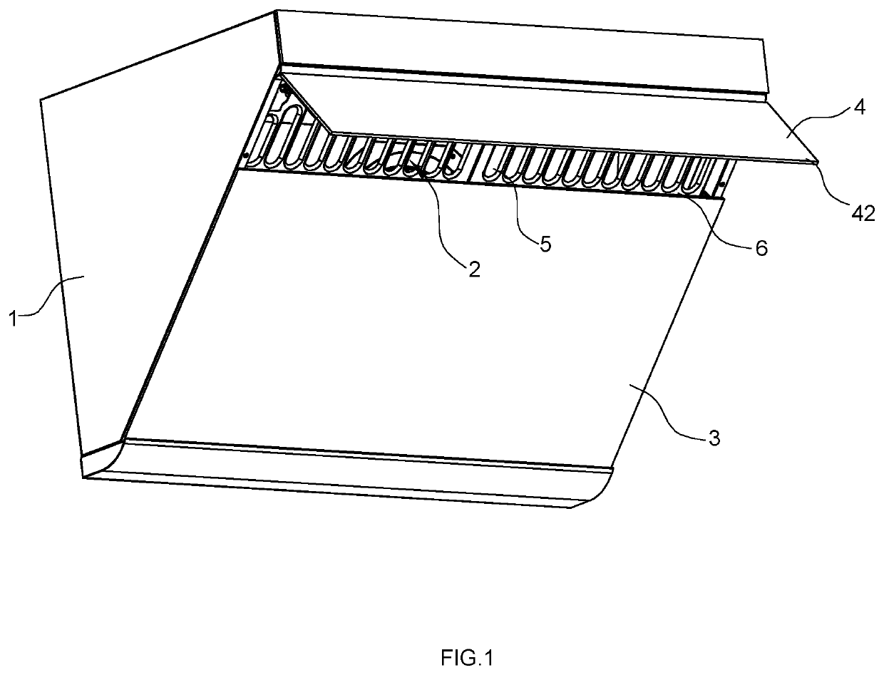
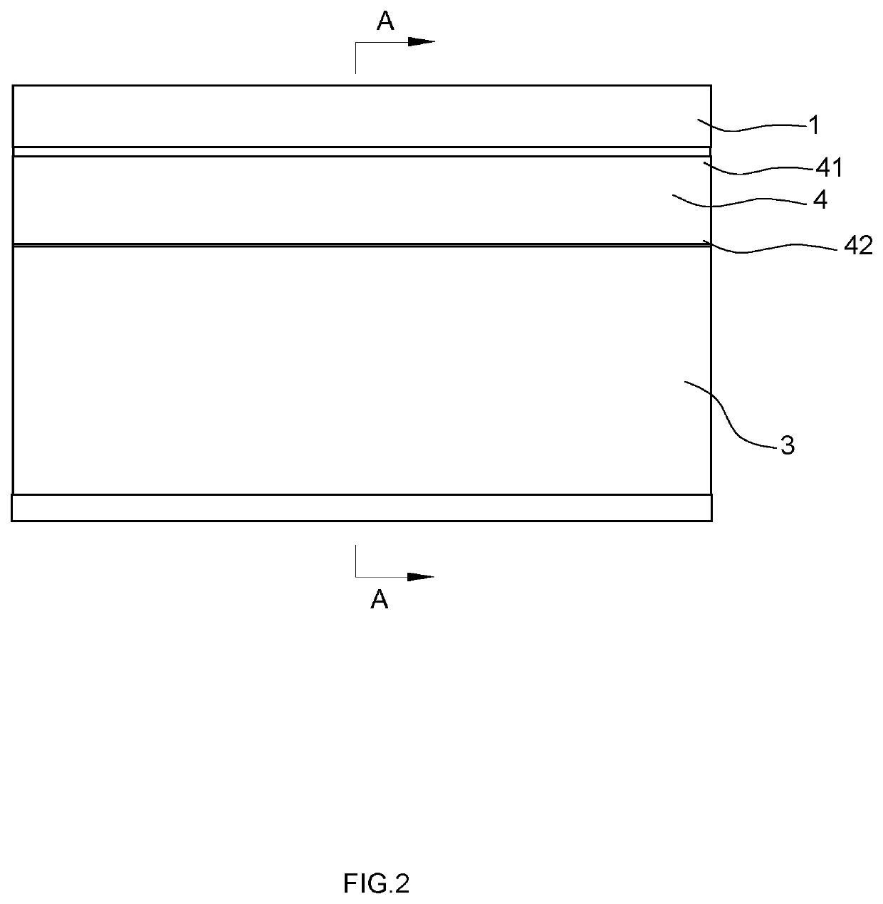
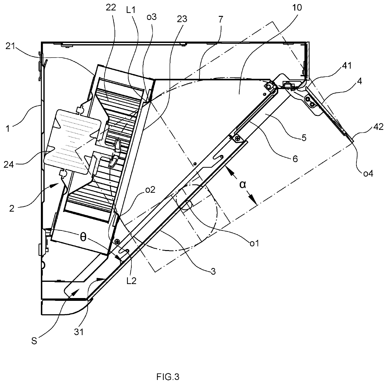
[0024]FIGS. 1-4 show a first embodiment of a range hood. The range hood comprises a housing 1 with a left side plate and a right side plate, a fan system 2 with a motor 24 and a rotary shaft, a front plate 3 with an air inlet 5 obliquely disposed between the left side plate and the right side plate of the housing 1, and a smoke deflector 4 rotatably assembled on the air inlet 5, enabling the air inlet 5 be open or close, an oil guide plate 7 with an air-intake hole 71 obliquely disposed between the left side plate and the right side plate of the housing 1, wherein the front plate 3 is located in front of the oil guide plate 7 covering the oil guide plate 7 and disposed away from the oil guide plate 7, the fan system 2 has air-intake ring 23 which is disposed around in the air-intake hole 71. A smoke trapping cavity 10 is enclosed by the oil guide plate 7, the front plate 3 and a corresponding portion of the housing 1.

[0025]In this embodiment, the fan system 2 is a single-fan system....

embodiment 2

[0031]FIGS. 6-9 show a second embodiment of a range hood. The second embodiment differs from the first embodiment in that, the fan system 2 in this embodiment is a double-fan system. Two identical impellers 22, air-intake rings 23 and motors 24 are arranged, side by side, in a volute 21 of the fan system 2. Correspondingly, two suction ports 71 are disposed side by side on the oil guide plate 7, with one air-intake ring 23 disposed on each of the suction ports 71. In addition, there are points fitting the Fibonacci spiral line described in Embodiment 1 at corresponding positions of the vertical section of the rotary center shaft of each motor 24 (as shown in FIG. 8), and the technical effects described in Embodiment 1 can be achieved (as shown in FIG. 5).


PUM


Abstract

The present invention discloses a range hood, during work, when the smoke deflector is opened to a maximum angle, a plurality of points fitting with a Fibonacci spiral line are arranged on a vertical section along the center of the rotary shaft of the motor, a starting point of the Fibonacci spiral line is arranged on an inner surface of the front plate below the air inlet, a top arc line at the top of the air-intake ring, a bottom arc line at the bottom of the air-intake ring are respectively tangent to a curve with a radius of Fibonacci sequence Fn-1, and an endpoint of the free edge of the smoke deflector coincides with an endpoint of a curve with a radius of Fibonacci sequence Fn. In the present invention, the smoke can more smoothly enter a smoke trapping cavity of the range hood. A sufficient residence space is provided for a large amount of smoke generated by the stove, and smoke is effectively prevented from escaping from the smoke trapping cavity.

Description

FIELD OF THE INVENTION[0001]The present invention relates to the technical field of kitchen appliances, and in particular to a range hood.DESCRIPTION OF THE PRIOR ART[0002]At present, there are a variety of range hoods in the market, for example, European-style range hoods, deep-suction range hoods, close-suction range hoods and the like, among which the close-suction range hoods become increasingly popular due to their novel and changeable appearance, the small distance between the smoke inlet and the smoke source and other advantages. For example, Chinese patents CN201476136U (Patent No.: 200920195669.5) and CN103574721B (Patent No.: 201310524779.2), disclosed the side-suction range hoods.[0003]Common close-suction range hoods are wall-mounted in an oblique triangle. Although the close-suction range hoods have a lower smoke inlet than other types of range hoods, due to the large distance between the burner of the stove and the wall surface in practical applications, such range hoo...

Claims


Application Information

Patent Timeline
IPC IPC(8): F24C15/20
CPCF24C15/2042F24C15/20
Inventor XU, ZHINENG
Owner NINGBO FOTILE KITCHEN WARE CO LTD
Why Eureka
Try Eureka