Automated teller machine

a technology teller machine, which is applied in the direction of automatic teller machine, atm details, instruments, etc., can solve the problems of increasing atm implementation costs and times

Inactive Publication Date: 2008-04-24
NCR CORP
View PDF6 Cites 7 Cited by
  • Summary
  • Abstract
  • Description
  • Claims
  • Application Information

AI Technical Summary

Benefits of technology

[0004]It is an object of the present invention to provide an ATM which addresses as least some of the problems detailed above.

Problems solved by technology

There are a number of issues with current ATM designs including product packaging, cost points, and product variants.
This increases ATM implementation costs and times.

Method used


Image

  • Automated teller machine
  • Automated teller machine
  • Automated teller machine

Examples


Embodiment Construction

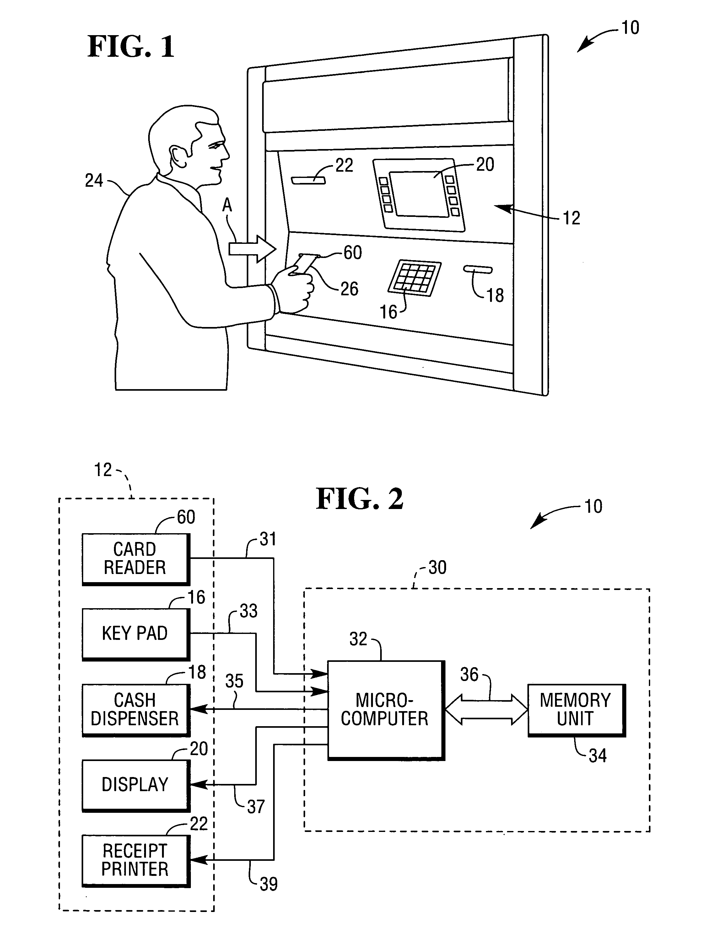
[0017]The present invention is directed to an ATM. The specific construction of the ATM may vary. An ATM head unit 10 embodying the present invention is illustrated in FIGS. 1 and 2.

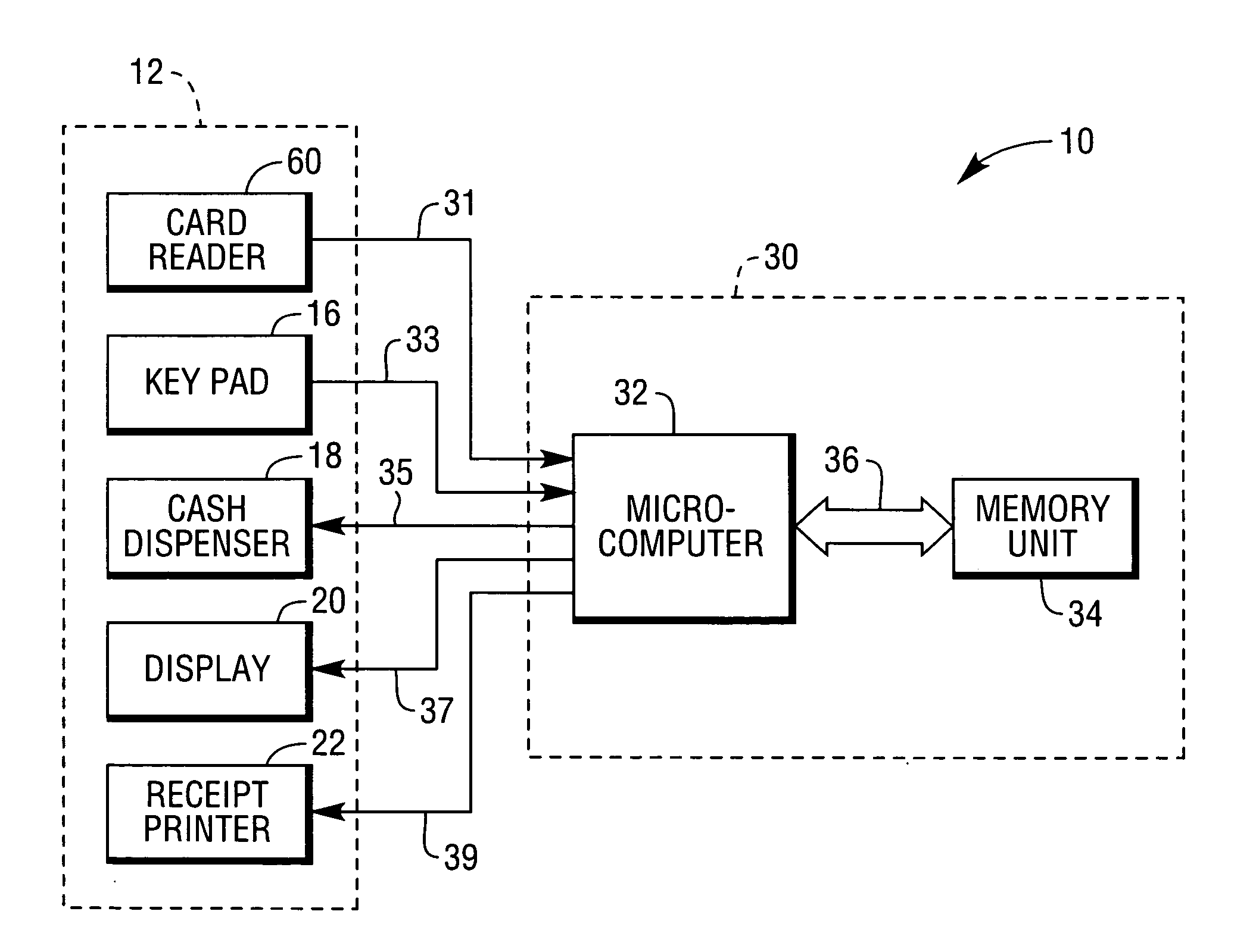
[0018]The ATM includes a head unit 10 comprises a user interface in the form of a front panel 12. The front panel 12 includes a card reader 60, a key pad 16, a cash dispenser slot 18, a display 20, and a receipt printer 22. As particularly shown in FIG. 1, the card reader 60 has a card entry slot through which a customer 24 can insert a user identification card 26 at the commencement of a transaction to be conducted by the customer. The cash dispenser has a cash slot 18 through which cash currency notes stored inside the security enclosure of the ATM can be delivered to the customer 24 during the transaction. The receipt printer 22 has a receipt slot through which a receipt of the transaction is delivered to the customer 24 at termination of the transaction.

[0019]When the customer 24 inserts the user ide...


PUM


Abstract

An ATM comprises a) an ATM head unit in the form of a housing within which are housed user interface components of an ATM; and b) a security enclosure within which is located an ATM media dispenser. The security enclosure and the head unit are discrete physically separate units, which are coupled so that media from the security enclosure can be dispensed to a user through interaction with the head unit, when in use.

Description

BACKGROUND OF THE INVENTION[0001]The present invention relates to an Automated Teller Machine (ATM).[0002]There are a number of issues with current ATM designs including product packaging, cost points, and product variants. By providing one low cost assembly for through-the-wall, in-lobby, and free standing ATMs this invention addresses those issues.[0003]In addition, the invention looks at a revolutionary re-think of the way in which a user interface of an ATM is presented to users. In the past an ATM has taken up a significant floor area of a financial institution or outdoor space. Also, in through-the-wall ATMs there has been a need for significant building work including cutting a hole in a wall of approximately the dimensions of the present user interface. This increases ATM implementation costs and times.SUMMARY OF THE INVENTION[0004]It is an object of the present invention to provide an ATM which addresses as least some of the problems detailed above.[0005]In accordance with ...

Claims


Application Information

Patent Timeline
Patent Type & Authority Applications(United States)
IPC IPC(8): G07F19/00G06F7/08
CPCG07F19/205G07F19/20
Inventor HENDERSON, JAMES
Owner NCR CORP
Why Eureka
Try Eureka