Clamp for use in wire harness

a technology for wire harnesses and clamps, which is applied in the direction of mechanical equipment, other domestic objects, machine supports, etc., can solve the problems of large force required to unlock the clamp from the locking hole, and the difficulty of disassembly of the vehicle body, etc., and achieves reliable fixing, resists flexing of the stems, and removes easily from the vehicle body

Inactive Publication Date: 2008-04-24
SUMITOMO WIRING SYST LTD
View PDF8 Cites 9 Cited by
  • Summary
  • Abstract
  • Description
  • Claims
  • Application Information

AI Technical Summary

Benefits of technology

[0019] The thickness of each of the stems preferably is small and equal to the thickness of the spanning part. Additionally, the stems are flexible so that the spanning part flexes easily in a shape of V into the cavity surrounded by the left and right stems, the spanning part, and the plate.
[0020] The above-described construction allows the left and right vanes to flex more and enables the clamp to be unlocked from the vehicle body by a low pull-out force. Thus, the wire harness can be removed easily from the vehicle body.
[0021] On the other hand, the provision of two stems enables the vanes to hold the vehicle body with a sufficient locking force even though each of the stems is thin. The spanning part is between the two stems and resists flexing of the stems when the wire harness is locked to the vehicle body. Further the tip of each vane preferably has a multi-step vehicle body-lock. After the clamp is locked to the vehicle body, a desired step of the vehicle body-lock of the vane can be locked securely to the periphery of the locking hole. Therefore, the wire harness is fixed reliably to the vehicle body and will not be loosened by vibration of the vehicle body.
[0022] The spanning part may have at least one groove. Additionally, the vane supports may have substantially the same thickness as the spanning part. The groove serves as the support for twist so that the vanes flex and twist about the groove. Thus when the wire harness is pulled in the removal direction from the vehicle body, a stress concentrates on the groove as the support for twist. Thus, the stems flex in and towards one another. Further, the stems are shifted from each other to project in a point symmetry, and the vanes rotate torsionally about the groove. Therefore it is possible to decrease the pulling force to unlock the vehicle body-locking steps of the vanes from the locking hole of the vehicle body. Rotation of the vanes causes the locking steps at the tips of the vanes to move in a direction to unlock from the peripheral edge of the locking hole. Thus, the clamp is unlocked from the vehicle body and the wire harness can be pulled so that the vanes of the clamp can be taken out of the locking hole.

Problems solved by technology

The wire harness may have to be replaced in a manufacturing process and may have to be exchanged when the wire harness has trouble during use.
Additionally, the pulling force is applied only to the concave part, and hence a large force is required to unlock the clamp from the locking hole.
Thus it is difficult to disassemble the vehicle body.

Method used


Image

  • Clamp for use in wire harness
  • Clamp for use in wire harness
  • Clamp for use in wire harness

Examples


second embodiment

[0076] The second embodiment enables the wire harness W / H to be removed from the mounted condition on the vehicle body 30 shown in FIG. 10A by pulling the wire harness W / H strongly in the removal direction. As shown in FIG. 10B, the pulling force applied to the wire harness W / H, with concentrates stress on the V-shaped groove 20a. Thus, the left and right stems 15A, 15B and the left and right vanes 16A, 16B flex towards the cavity and about the groove 20a serving as a torsional rotation support P.

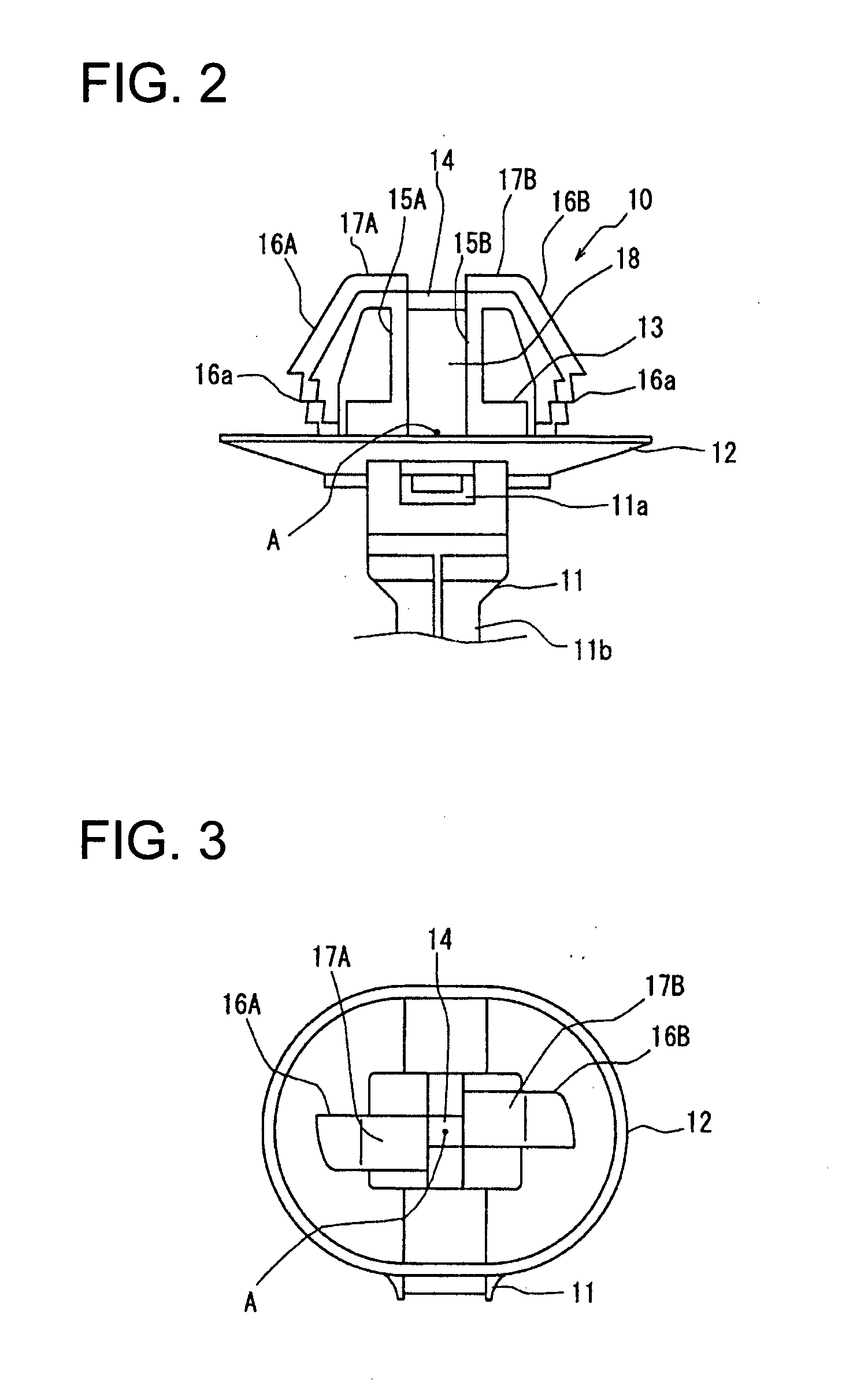
[0077] The left and right stems 15A, 15B are symmetrical with respect to the central point A of the clamp 10B. Thus, when the wire harness W / H is pulled farther, a torsional rotation about the torsional rotation point P is induced with the left stem 15A and the left vane 16A integral with each other, and with the right stem 15B and the right vane 16B integral with each other.

[0078] The vehicle body-locking part 16a of the vane 16 is unlocked from the left and right peripheral edges of the ...

third embodiment

[0084]FIGS. 12 and 13 show a clamp 10C according to a The spanning part 20-3 does not have a groove at the center to support twist, but rather has grooves 20a3, 20b3 as the supports for twist at positions corresponding to the tips of the left and right stems 15A, 15B.

[0085] The third embodiment is different from the second embodiment in the above-described construction, but other constructions of the third embodiment are similar to those of the second embodiment.

[0086] In the above-described construction, in removing the wire harness W / H from to which the wire harness W / H is fixed the vehicle body 30 by the clamp 10C, as shown in FIG. 13A. The wire harness W / H can be removed from the vehicle body 30 by pulling the wire harness away from the vehicle body, as in the other embodiments. Thus, as shown in FIG. 13B stress concentrates on the V-shaped grooves 20a3, 20b3, and the left and right vanes 16A, 16B incline and flex with the grooves 20a3, 20b3 serving as supports for twist and s...

first embodiment

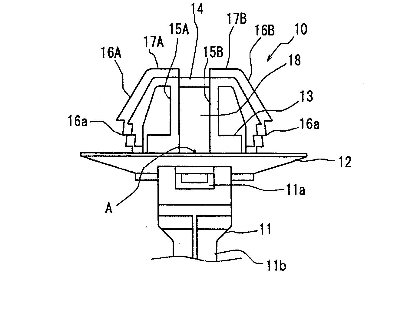
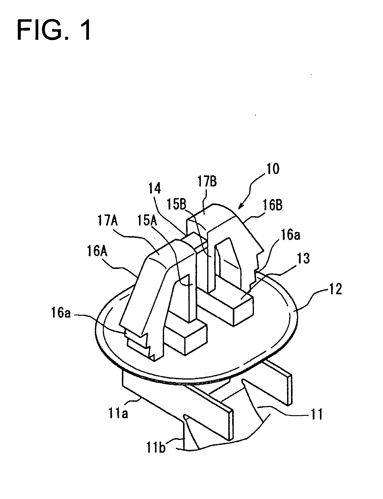
[0095] The stems 15A and 15B and the vanes 16A, 16B are inserted into the locking hole 30a of the vehicle body 30, as in the More particularly, the left and right vanes 16A, 16B are pressed into the locking hole 30a by flexing the vanes 16A, 16B towards the stems 15A and 15B. The left and right vanes 16a, 16B elastically return to their original state when the vanes 16A, 16B are pressed completely into the locking hole 30a. As a result, the vehicle body-locking stepped parts 16a at the tip of the each of the left and right vanes 16A, 16B lock to the periphery of the locking hole 30a at the back side of the vehicle body 30. Thus, as shown in FIGS. 19A and 20A, the wire harness W / H is fixed to the vehicle body 30 through the clamp 10D.

[0096]FIGS. 19 through 21 show steps of removing the wire harness W / H from the vehicle body. Initially the wire harness W / H is pulled at a strong force in a direction in which the wire harness W / H is removed from the vehicle body 30, as in the first emb...


PUM


Abstract

A clamp (10) has a plate (12) with a harness-mounting part (11) to be fastened to a wire harness. Two spaced-apart stems (14) project from the plate (12). A spanning part (14) connects confronting portions of the stems (15) to form a cavity (18). A vane support (17) projects out from the end of each stem (15) and a vane (16) projects down and out from a tip of each vane support (17). A vehicle body-locking part (16a) formed at a tip of each vane (16). The spanning part (14) twists towards the cavity (18) when the wire harness is pulled in a withdrawal direction from the vehicle body to unlock the vehicle body-locking parts (16a) of the vanes (16) from the locking hole.

Description

BACKGROUND OF THE INVENTION [0001] 1. Field of the Invention [0002] The invention relates to a clamp for use in a wire harness and more particularly to a clamp for use in a wire harness which allows the wire harness to be removed easily from a vehicle body for replacing the wire harness wired thereon and disassembling the vehicle body. [0003] 2. Description of the Related Art [0004] Substrate-type clamps and band-type clamps have been proposed for fixing a wire harness to a vehicle body. FIGS. 23A-23C herein show a substrate-type clamp that has a substrate 2 and a clamping part 3 formed integrally of synthetic resin. The clamping part 3 has a vane 3a and a locking step 3b is formed at the tip of the vane 3a. The substrate 2 is mounted on the periphery of a wire harness W / H with a tape T and the vane 3a of the clamping part 3 is inserted into a locking hole 4a of a vehicle body 4. Thus, the locking step 3b of the vane 3a is locked securely to the peripheral edge of the locking hole 4...

Claims


Application Information

Patent Timeline
Patent Type & Authority Applications(United States)
IPC IPC(8): A47F5/08
CPCH02G3/30F16L3/137
Inventor DOI, MASAYUKIMORII, TOSHITSUGUOYAMADA, SHIGERU
Owner SUMITOMO WIRING SYST LTD
Why Eureka
Try Eureka