Manufacturing device and manufacturing method for optical disc

US20080093755A1Inactive Publication Date: 2008-04-24ORIGIN ELECTRIC CO LTD

Image

  • Manufacturing device and manufacturing method for optical disc
  • Manufacturing device and manufacturing method for optical disc
  • Manufacturing device and manufacturing method for optical disc

Examples


first embodiment

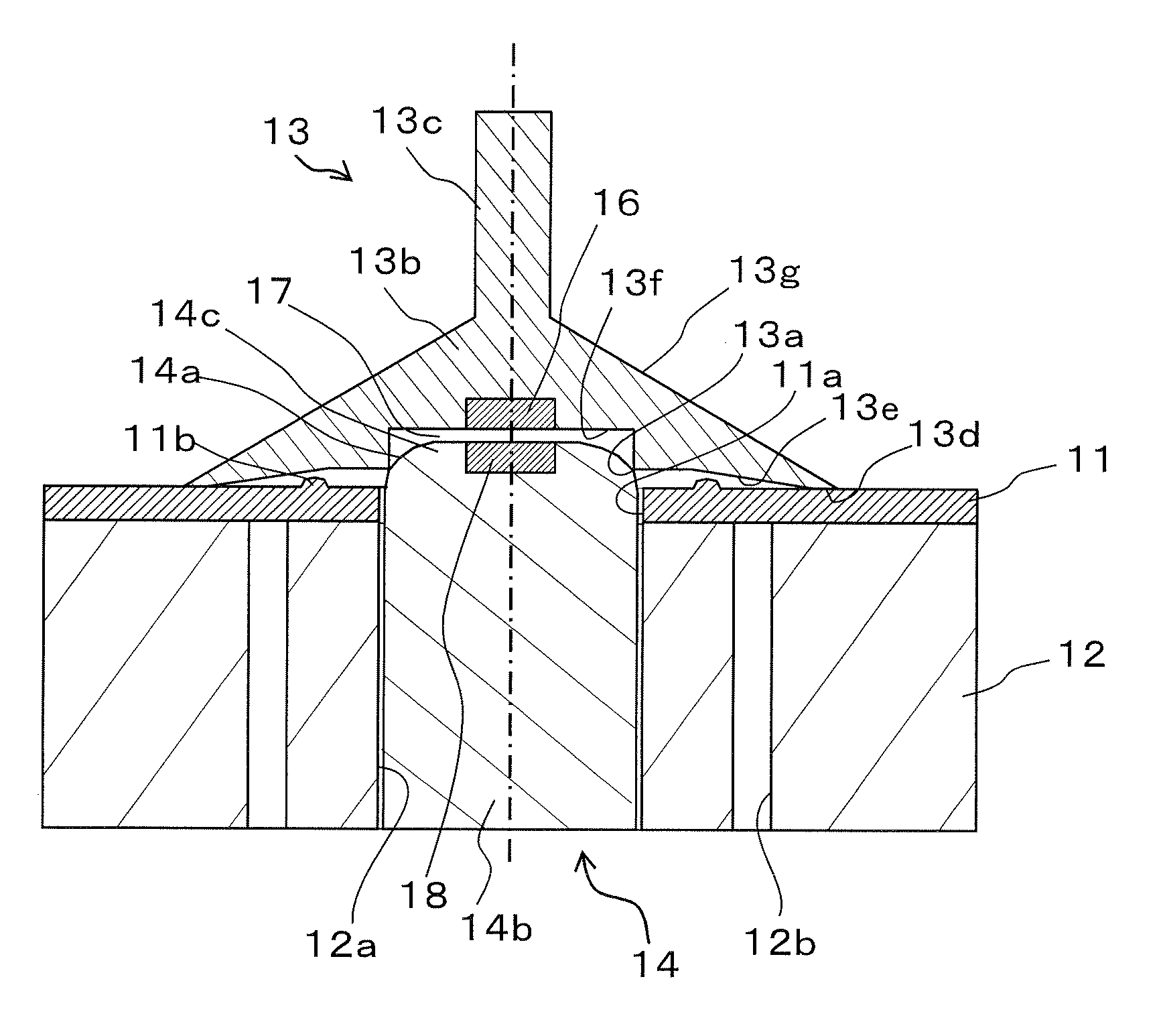
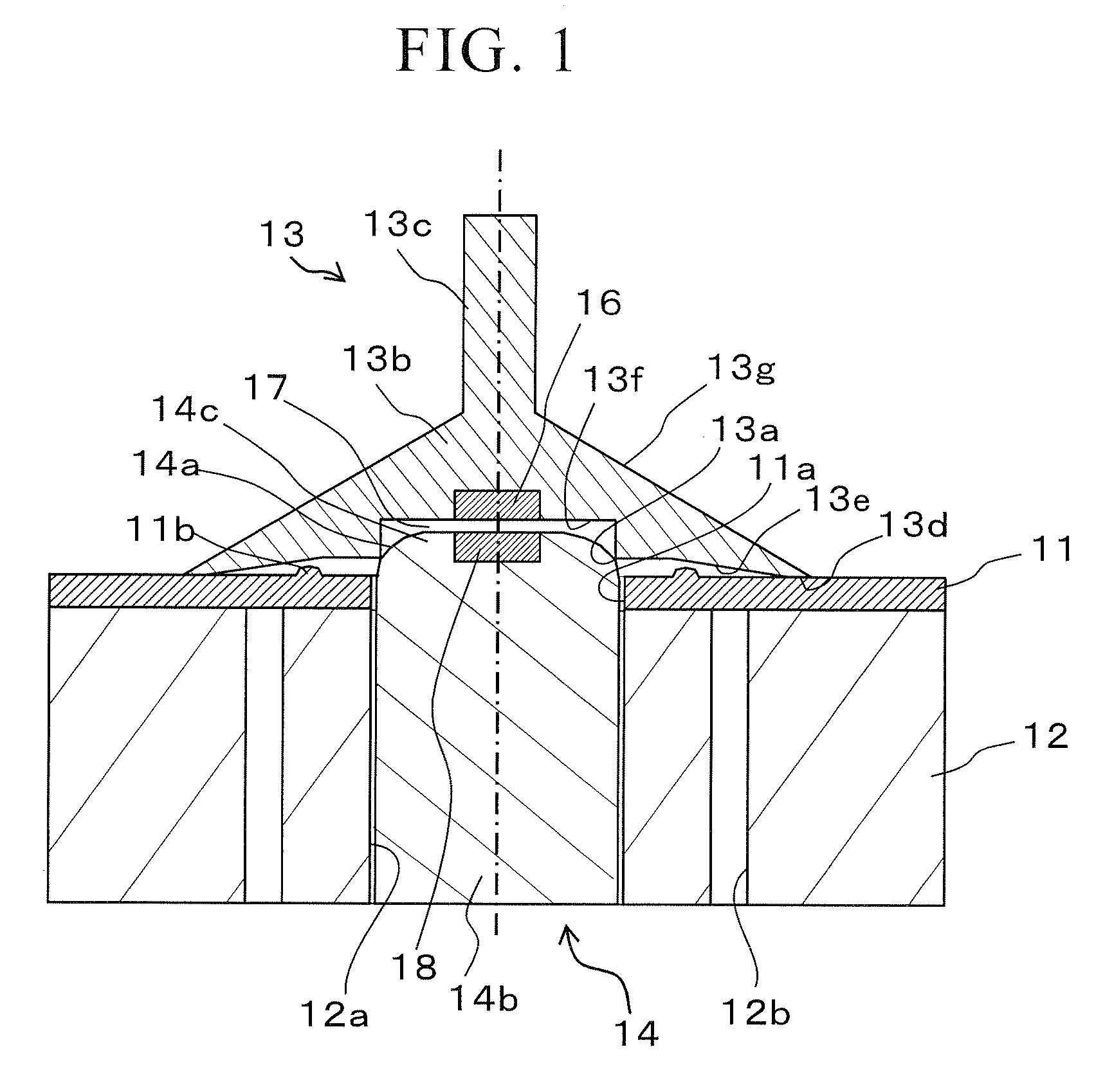
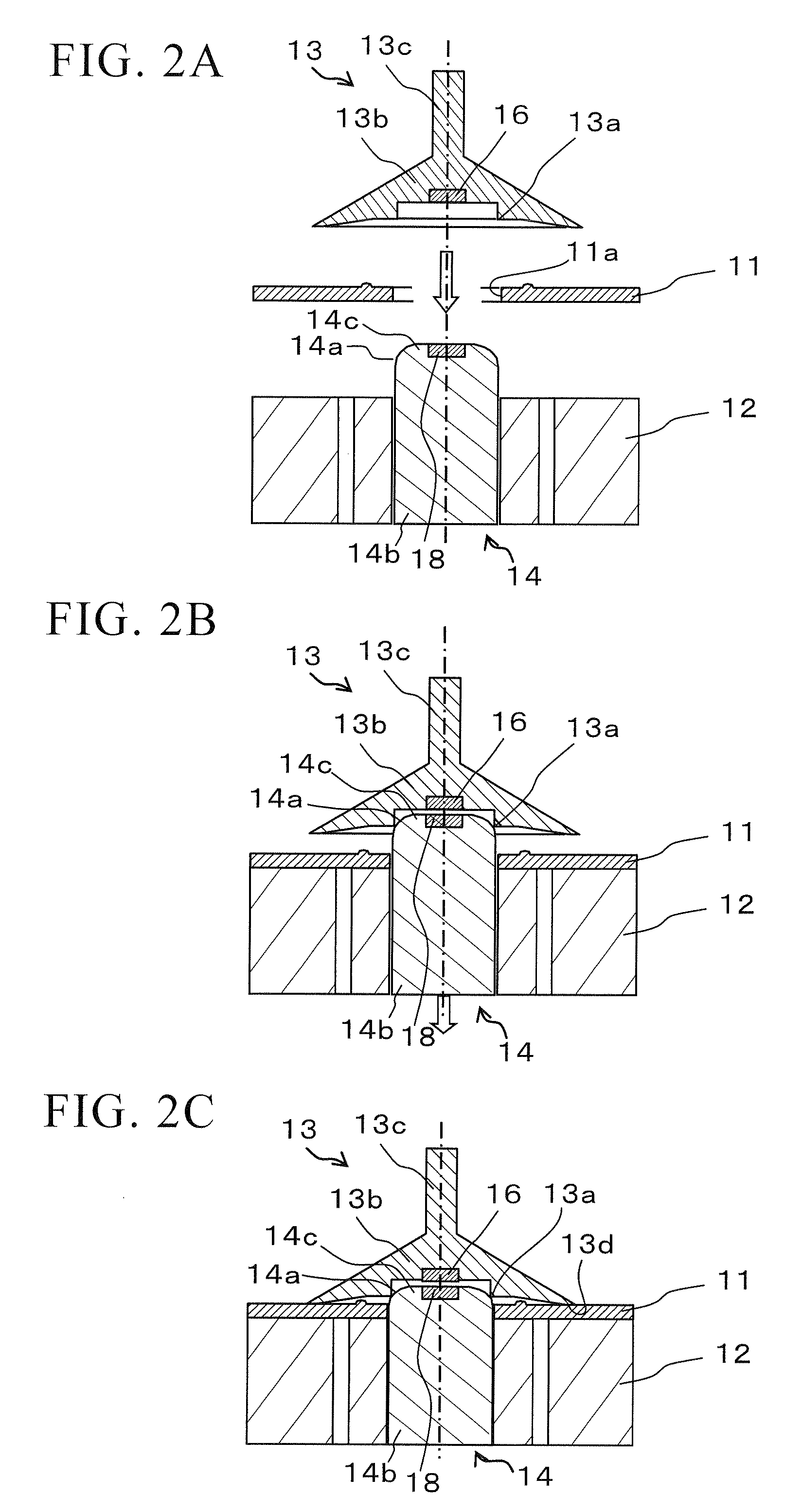
[0034]FIG. 1 shows a cross-sectional view of a manufacturing device for an optical disc, according to a first embodiment of the present invention. A disc substrate 11 is placed on a disc-supporting base 12, and a pin-shaped member 14 arranged in a center hole 12a of the disc-supporting base 12 is inserted in a center hole 11a of the disc substrate 11. The disc substrate 11 is vacuum-absorbed by a non-illustrated vacuuming device through plural of vacuuming holes 12b formed in the disc-supporting base 12. The center hole 11a of the disc substrate 11 is closed by a capping member 13 placed on the disc substrate 1. The disc-supporting base 12 and the pin-shaped member 14 are connected to a non-illustrated rotation device. The liquid material is supplied onto the capping member 13 that closes the center hole 11a of the disc substrate 11, while rotating the disc-supporting base 12 in a low speed; and thereafter, the disc-supporting base 12 and the pin-shaped member 14 are rotated in a hi...

second embodiment

[0051]FIG. 5 shows a cross-sectional view of a manufacturing device for an optical disc, according to a second embodiment of the present invention. In the following explanation, explanations for the same constitute elements as those of the above-mentioned first embodiment shown in FIG. 1 are omitted here, and the differences will be explained below. The present embodiment mainly differs in the following points from the first embodiment in which the capping member 13 has the circular-shaped supported portion 13a while the pin-shaped member 14 has the supporting portion 14a formed in the arc-shaped cross-section for receiving the supported portion 13a. That is, the present embodiment has a capping member 23 having a spherical-shaped supported portion 23a formed at the center of a back face thereof, and a pin-shaped member 24 having a bowl-shaped supporting portion 24a formed at the top center of a protruding section 24c for supporting the spherical-shaped supported portion 23a.

[0052]...


PUM


Abstract

This manufacturing device for an optical disc includes: a disc-supporting base on which a disc substrate is mounted; a pin-shaped member arranged at a center of the disc-supporting base, and is movable in the vertical in a center hole of the disc substrate; and a capping member which is slidably placed on a top of the pin-shaped member, and closes the center hole of the disc substrate, wherein when the capping member placed on the top of the pin-shaped member is lowered such that a back face of the capping member contacts an around of the center hole of the disc substrate mounted on the disc-supporting base, the capping member slides on the top of the pin-shaped member.

Description

BACKGROUND OF THE INVENTION [0001] Priority is claimed on Japanese Patent Application No. 2006-288947, filed Oct. 24, 2006, the contents of which are incorporated herein by reference. FIELD OF THE INVENTION [0002] The present invention relates to a manufacturing device and a manufacturing method for an optical disc, which can prevent involving bubbles while forming a protective film on a disc substrate or while forming an adhesive layer between disc substrates. DESCRIPTION OF THE RELATED ART [0003] In a conventional manufacturing method of an optical disc, when a protective film is formed on a surface of a disc substrate as an optical transparent layer, or when a adhesive layer is formed on one of or both of disc substrates in order to bond two or more of the disc substrates, a center hole of the disc substrate is closed by a capping member, and a liquid material is supplied onto the capping member. Thereafter, the liquid material uniformly outspreads over the entire surface of the ...

Claims


Application Information

Patent Timeline
24 Apr 2008
Publication
US20080093755A1
IPC
B29D17/00; B32B37/12
CPC
B32B37/003; B32B37/12; B32B2038/1891; Y10T156/1744; B32B2429/02; G11B7/26; Y10S425/81; B32B2309/68
Inventors
NISHIMURA, HIRONOBU; NAKAMURA, MASAHIRO