Manufacturing device and manufacturing method for optical disc
a manufacturing method and technology of optical disc, applied in the field of manufacturing devices and optical disc manufacturing methods, can solve the problems of high possibility of bubbles, problems in the quality and appearance of the disc substrate, and errors in writing and reading information, so as to facilitate the flatness of the disc substrate and increase the contact
- Summary
- Abstract
- Description
- Claims
- Application Information
AI Technical Summary
Benefits of technology
Problems solved by technology
Method used
Image
Examples
first embodiment
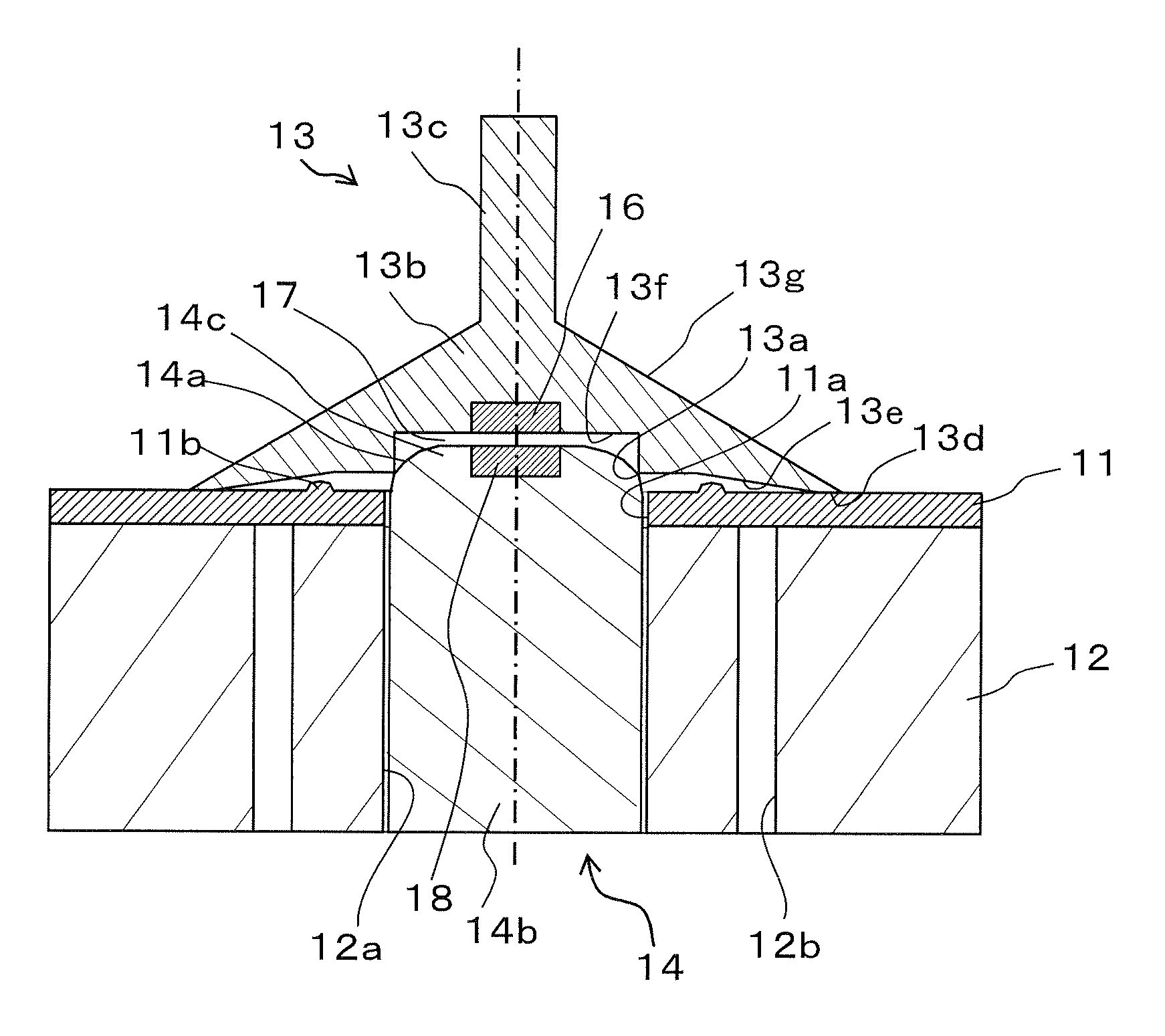
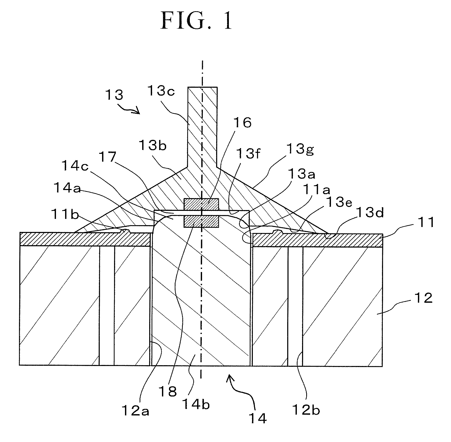
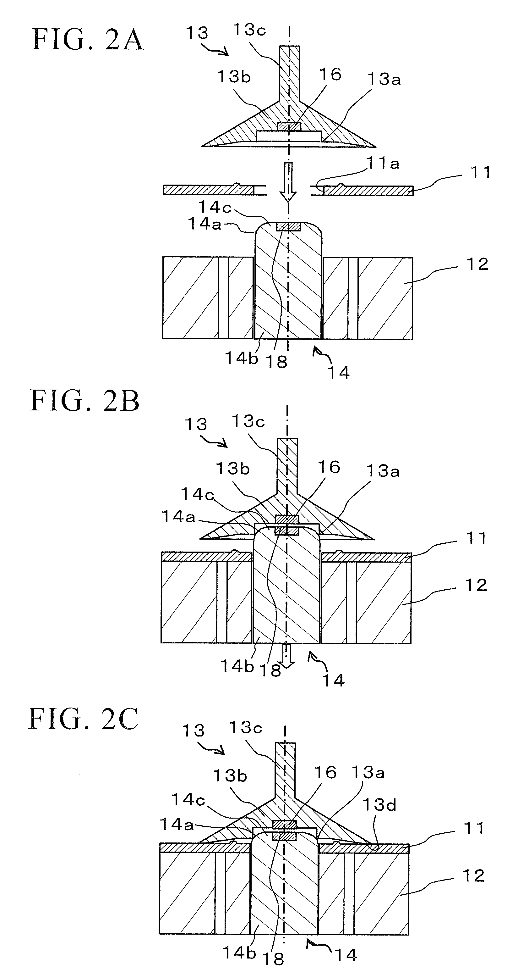
[0036]FIG. 1 shows a cross-sectional view of a manufacturing device for an optical disc, according to a first embodiment of the present invention. A disc substrate 11 is placed on a disc-supporting base 12, and a pin-shaped member 14 arranged in a center hole 12a of the disc-supporting base 12 is inserted in a center hole 11a of the disc substrate 11. The disc substrate 11 is vacuum-absorbed by a non-illustrated vacuuming device through plural of vacuuming holes 12b formed in the disc-supporting base 12. The center hole 11a of the disc substrate 11 is closed by a capping member 13 placed on the disc substrate 1. The disc-supporting base 12 and the pin-shaped member 14 are connected to a non-illustrated rotation device. The liquid material is supplied onto the capping member 13 that closes the center hole 11a of the disc substrate 11, while rotating the disc-supporting base 12 in a low speed; and thereafter, the disc-supporting base 12 and the pin-shaped member 14 are rotated in a hi...
second embodiment
[0053]FIG. 5 shows a cross-sectional view of a manufacturing device for an optical disc, according to a second embodiment of the present invention. In the following explanation, explanations for the same constitute elements as those of the above-mentioned first embodiment shown in FIG. 1 are omitted here, and the differences will be explained below. The present embodiment mainly differs in the following points from the first embodiment in which the capping member 13 has the circular-shaped supported portion 13a while the pin-shaped member 14 has the supporting portion 14a formed in the arc-shaped cross-section for receiving the supported portion 13a. That is, the present embodiment has a capping member 23 having a spherical-shaped supported portion 23a formed at the center of a back face thereof, and a pin-shaped member 24 having a bowl-shaped supporting portion 24a formed at the top center of a protruding section 24c for supporting the spherical-shaped supported portion 23a.
[0054]...
PUM
| Property | Measurement | Unit |
|---|---|---|
| inner diameter | aaaaa | aaaaa |
| inner diameter | aaaaa | aaaaa |
| outer diameter | aaaaa | aaaaa |
Abstract
Description
Claims
Application Information
 - R&D
- Intellectual Property
- Life Sciences
- Materials
- Tech Scout
- Unparalleled Data Quality
- Higher Quality Content
- 60% Fewer Hallucinations
Browse by: Latest US Patents, China's latest patents, Technical Efficacy Thesaurus, Application Domain, Technology Topic, Popular Technical Reports.
© 2025 PatSnap. All rights reserved.Legal|Privacy policy|Modern Slavery Act Transparency Statement|Sitemap|About US| Contact US: help@patsnap.com


