Cabin door device

Active Publication Date: 2008-04-24
KUBOTA LTD
View PDF15 Cites 39 Cited by
  • Summary
  • Abstract
  • Description
  • Claims
  • Application Information

AI Technical Summary

Benefits of technology

[0007]The object of the invention is to solve or alle

Problems solved by technology

For this reason, problems arise in that, e.g., the arrangement of equipment in the cabin will be limited, and in that, when luggage or the like is placed in a positio

Method used


Image

  • Cabin door device
  • Cabin door device
  • Cabin door device

Examples


Example

[0026]Preferred embodiments of the present invention shall be described below with reference to the accompanying drawings. A plurality of embodiments shall be described. However, combinations of characteristics disclosed in the specified embodiments and characteristics disclosed in the other embodiments are included within the scope of the present invention.

[0027](Overall Structure of Utility Vehicle)

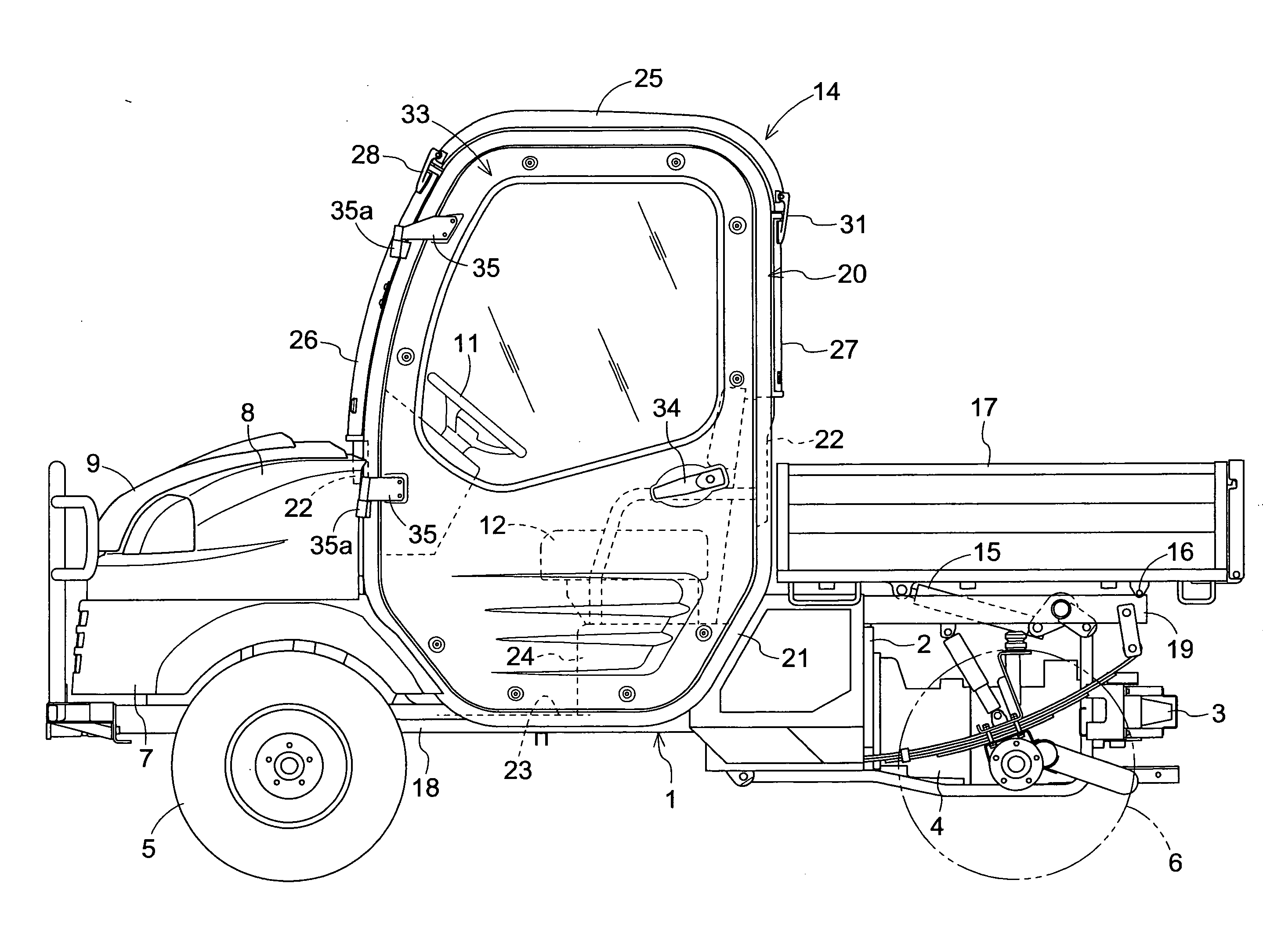
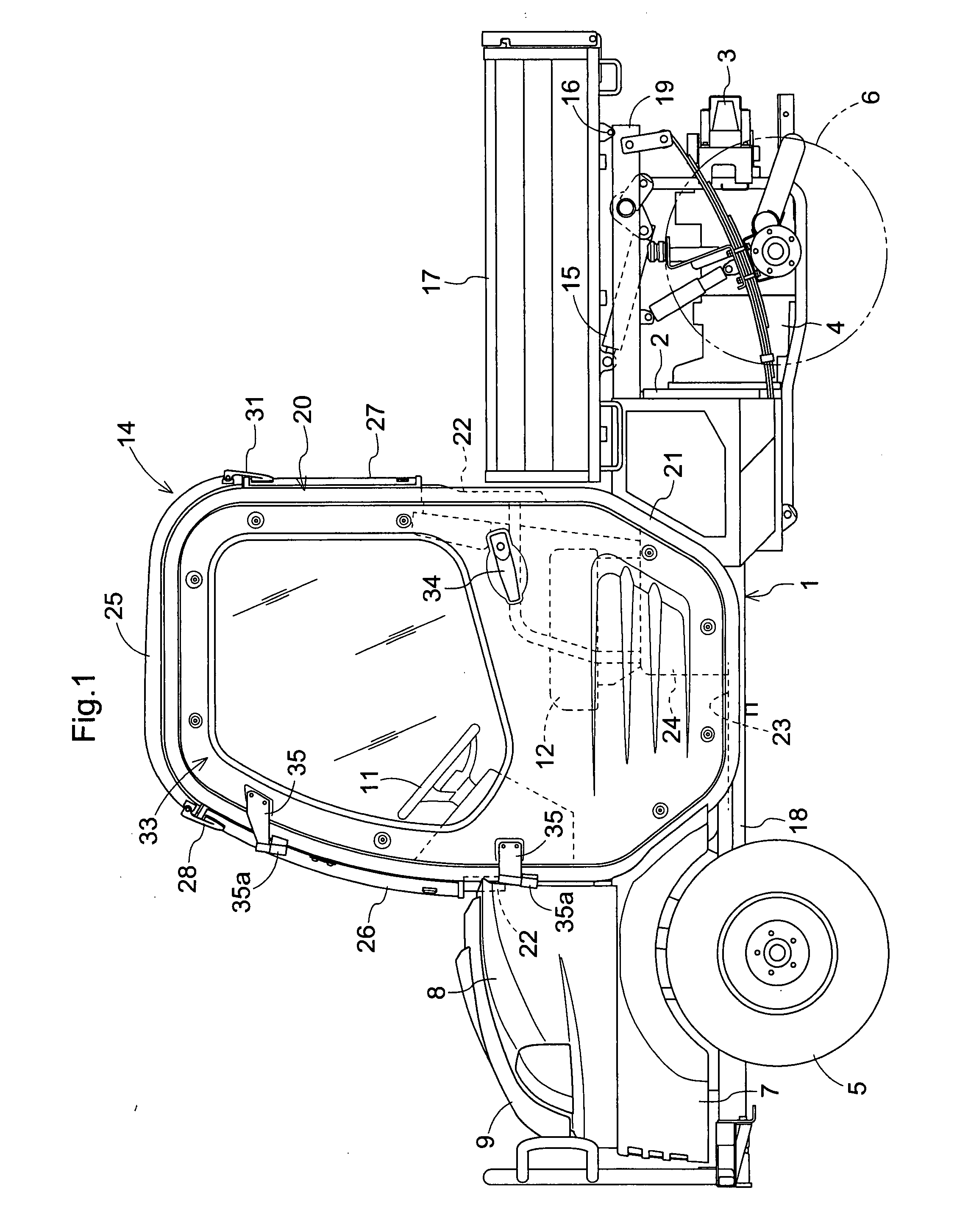
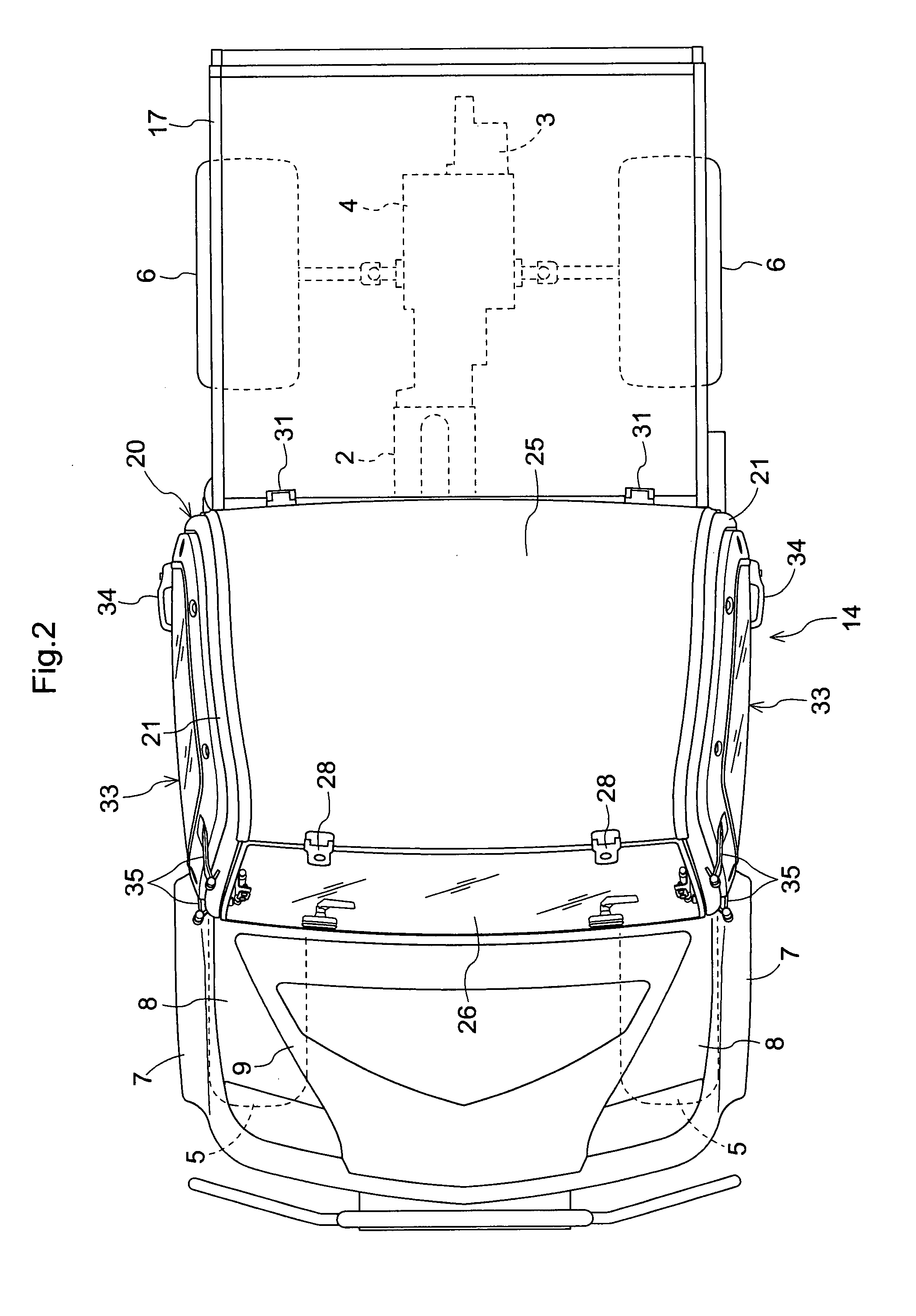
[0028]FIG. 1 shows a side view of the entirety of a utility vehicle that is an example of a work vehicle; and FIG. 2 shows a plan view of the entirety of the utility vehicle. In the utility vehicle, a motive force from an engine 2 supported by a vehicle body frame 1 in a vibration-proof state is transmitted to left and right pairs of front wheels 5 and rear wheels 6 via a gear-type transmission device 4 and a hydrostatic stepless transmission device 3 and the like, whereby a four-wheel drive is driven. A plan view of the utility vehicle in a state in which a door 33 is slightly open is ...


PUM


Abstract

A cabin door device having a cabin frame, comprises: a door mounted to a side part of the cabin frame so as to be moveable between a fully closed position and a fully open position; and a main striker supported by the cabin frame, wherein the door has a lock device, and the door is held in the fully closed position by the lock device engaging the striker; and an auxiliary striker that is supported by the cabin frame and whose position can be changed between a held posture, in which the door is held at an intermediate position between the fully closed position and the fully open position by coupling with the lock device, and a retracted position in which the lock device of the door is allowed to engage with the striker.

Description

BACKGROUND OF THE INVENTION[0001]1. Field of the Invention[0002]The present invention relates to a cabin door device to be mounted to a work vehicle or other vehicle.[0003]2. Description of the Related Art[0004]Prior art such as that disclosed in JP 13108182 and JP 3177081 is known in which an auxiliary striker changes to a held position in a lateral direction and links with a lock device to create a state in which a door is slightly open; and air within a cabin can be discharged or outside air can be brought into the cabin.[0005]In a conventional cabin door device disclosed in JP 13108182, an auxiliary striker is caused to rotate about 270°, whereby the auxiliary striker can be switched to a held position and a retracted posture. In a conventional cabin door device disclosed in JP 3177081, an auxiliary striker is caused to rotate about 180°, whereby the auxiliary striker can be switched to a held posture and a retracted posture.[0006]When the auxiliary striker is rotated or pivoted...

Claims


Application Information

Patent Timeline
IPC IPC(8): B60J10/08
CPCB60J5/0487E05B85/045Y10T16/61Y10S292/15E05C17/04Y10T292/683Y10T292/68
Inventor SHIBATA, TAKASHIHORIUCHI, YOSHIFUMIKAWAHARA, YOSHIHIROKOBAYASHI, MITSUGU
Owner KUBOTA LTD
Why Eureka
Try Eureka