Element Reduction In Phased Arrays With Cladding

a phased array and element reduction technology, applied in the field of phased arrays, can solve the problems of low control device cost, and low image reconstruction rate, and achieve the effect of improving image reconstruction rate, reducing image reconstruction rate, and reducing image quality

Active Publication Date: 2008-04-24
AGILENT TECH INC
View PDF2 Cites 23 Cited by
  • Summary
  • Abstract
  • Description
  • Claims
  • Application Information

AI Technical Summary

Benefits of technology

[0011]Sidelobe-free scanning in a phased array with element spacing greater than λ / 2 is accomplished by restricting maximum scan angles to less than λ / 2 radians and cladding the array with a metamaterial.

Problems solved by technology

Unfortunately, these advantages are often offset by a cost disadvantage.
In most traditional phased arrays, the control devices are expensive, and in some cases each may require one or more stages of amplification.
Sparse arrays are well known in the ultrasound and microwave / millimeter wave literature to create new problems, particularly the appearance of so called grating sidelobes.
For example, deconvolution algorithms can be applied, but the most successful of these are nonlinear algorithms which are both scene dependent and very time consuming.
An older, linear (and hence faster and more general) approach is Wiener-Helstrom filtering (ref), but it is well known in that it produces inferior image reconstruction compared to the nonlinear approaches (which are slower and more specialized) such as Maximum Likelihood (ML) iteration (ref) Correlation imaging, involving different subsets of an already sparse array, is also a nonlinear scheme which tends to be quite slow, i.e., not suitable for real-time use.
Obviously, this “solution” is inadequate in dealing with a highly dynamic environment.

Method used


Image

  • Element Reduction In Phased Arrays With Cladding
  • Element Reduction In Phased Arrays With Cladding
  • Element Reduction In Phased Arrays With Cladding

Examples


Embodiment Construction

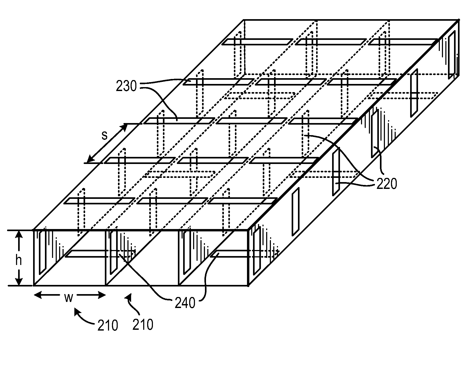
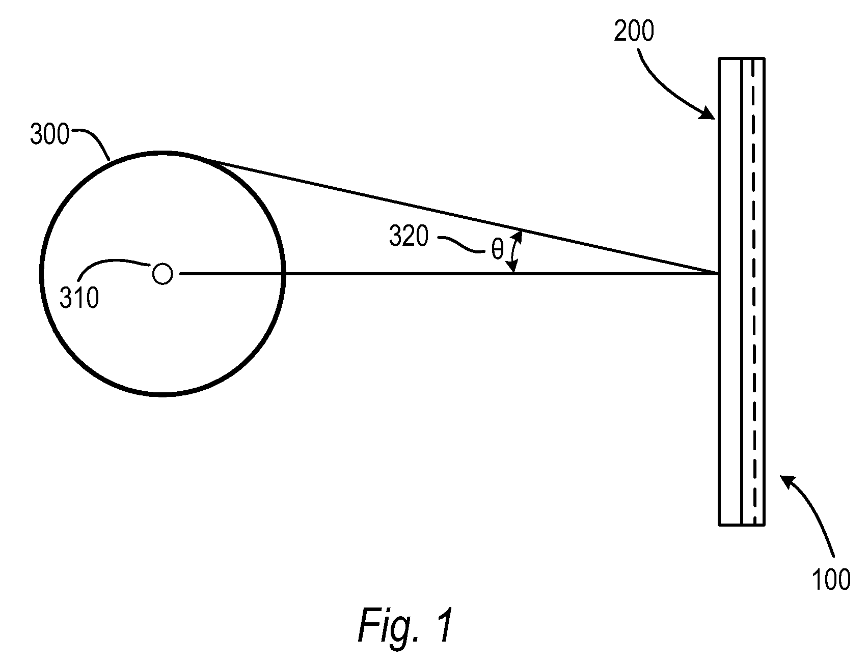
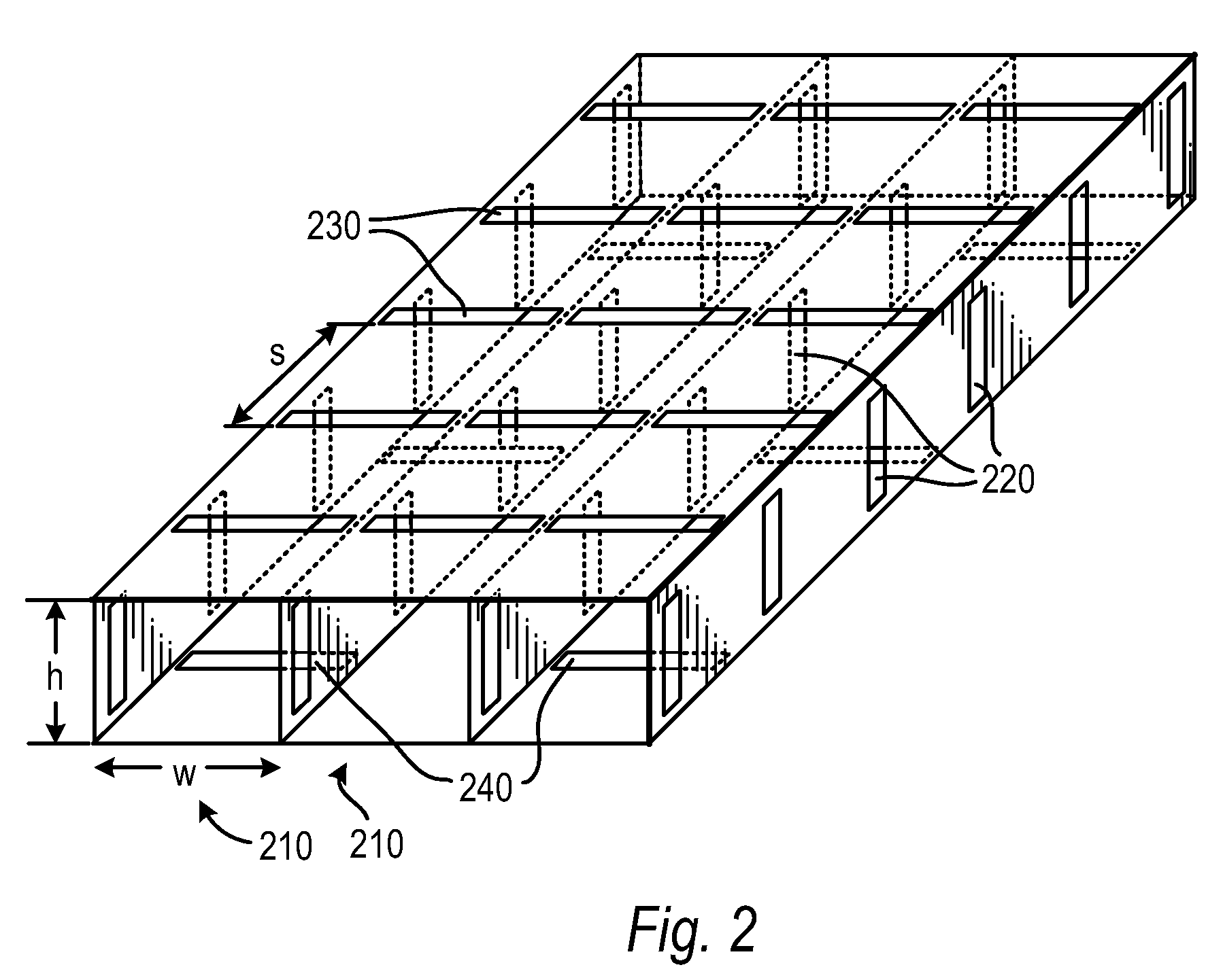
[0018]In phased-array systems, the commonly stated requirement for λ / 2 spacing between elements (where λ is the operating wavelength) arises from the desire to minimize sidelobes when scanning at angles up to π / 2 radians, or 90° from the scan center, which is a line normal to the plane of the array. Sparse arrays, where the element spacing is greater than λ / 2 create grating sidelobes for large scan angles. While post-processing approaches to reduce the ghosting introduced by these sidelobes exist the better ones are computationally expensive and scene dependent, making them impractical in dynamic environments such as security scanning.

[0019]In prototypical phased array applications such as the Distant Early Warning (DEW) radar system, or AEGIS AN / SPY-1 phased array radars, wide scan angles, up to 2 π steradians, are required. However, in many applications, a smaller solid angle scan field is sufficient. As an example, in security screening of individuals or objects, the scan solid a...


PUM


Abstract

Grating lobe free scanning in a phased array with sparse element spacing is obtained by restricting the maximum scan angle for elements in the array, and cladding the array. Array elements may be integrated into the cladding.

Description

CROSS-REFERENCE TO RELATED APPLICATIONS[0001]This application is related by subject matter to U.S. application patent Ser. No. 10 / 997,422, entitled “A Device for Reflecting Electromagnetic Radiation,” U.S. application patent Ser. No. 10 / 997,583, entitled “Broadband Binary Phased Antenna,” both of which were filed on Nov. 24, 2004, and U.S. Pat. No. 6,965,340, entitled “System and Method for Security Inspection Using Microwave Imaging,” which issued on Nov. 15, 2005.[0002]This application is further related by subject matter to U.S. application patent Ser. No. 11 / 088,536, entitled “System and Method for Efficient, High-Resolution Microwave Imaging Using Complementary Transmit and Receive Beam Patterns,” U.S. application patent Ser. No. 11 / 088,831, entitled “System and Method for Inspecting Transportable Items Using Microwave Imaging,” U.S. application for patent Ser. No. 11 / 089,298, entitled “System and Method for Pattern Design in Microwave Programmable Arrays,” U.S. application for...

Claims


Application Information

Patent Timeline
Patent Type & Authority Applications(United States)
IPC IPC(8): H01Q21/00
CPCH01Q21/065H01Q21/0006
Inventor LEE, GREGORY S.
Owner AGILENT TECH INC
Why Eureka
Try Eureka