Systems and methods using ground plane filters for device isolation

a filter and device isolation technology, applied in the field of system with ground planes, can solve the problems of affecting the amount of mutual coupling between antenna elements, affecting the performance of devices, and affecting the space between antenna elements in those systems, so as to reduce the effect of signals and/or eliminate the effect of signals

Active Publication Date: 2008-04-24
HONG KONG APPLIED SCI & TECH RES INST
View PDF7 Cites 53 Cited by
  • Summary
  • Abstract
  • Description
  • Claims
  • Application Information

AI Technical Summary

Benefits of technology

[0006]The present invention is directed to systems and methods for attenuating unwanted signals in a ground plane through use of a filter configured as a pattern in the ground plane. An example system includes two elements (e.g, antenna elements) with the filter positioned therebetween. The elements cause unwanted signals in the ground plane, and the filter is adapted to reduce and / or eliminate the effects of the signals from the system.
[0007]In one example, the filter is a simple ground plane structure that can reduce mutual coupling between closely-packed antenna elements. In such an example, the structure can include a slotted pattern etched onto a single ground plane upon which the antenna elements are disposed. The slotted configuration creates a filter that acts as an inductive / capacitive (LC) component in the ground plane, and the size and shape of the slots can be designed so that the filter attenuates certain frequencies known to be most prevalent and / or cause most interference. Similarly, the structure can be applied to reduce mutual coupling between three, four, or more radiating elements. The slotted single ground plane structure can be simple and cost-effective to fabricate in some embodiments.

Problems solved by technology

As antenna systems grow smaller, space between antenna elements in those systems becomes more scarce.
Not only does the spacing between antenna elements have the potential to affect the radiation pattern of a system, but it can also affect the amount of mutual coupling between antenna elements.
Mutual coupling is inductive / capacitive coupling between two or more antennas, and it can sometimes result in unwanted performance degradation by interfering with signals being transmitted or by causing an antenna element to radiate unwanted signals.
In such systems, the antenna elements can induce currents in the ground plane that travel to other antenna elements and increase undesired coupling.
However, such systems generally produce an inadequate amount of isolation.
However, such systems are expensive in terms of both space and money because of the complexity of the three-dimensional shapes of the structures.
Currently, no prior art system provides adequate isolation with a minimum of complexity.

Method used


Image

  • Systems and methods using ground plane filters for device isolation
  • Systems and methods using ground plane filters for device isolation
  • Systems and methods using ground plane filters for device isolation

Examples


Embodiment Construction

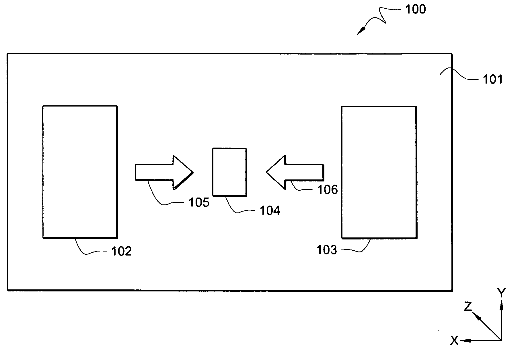
[0020]FIG. 1 is an illustration of exemplary system 100 adapted according to one embodiment of the invention. System 100 includes ground plane 101, which is typically a conductive layer of material disposed on a substrate (not shown), such as upon a layer of a Printed Circuit Board (PCB). In some embodiments, ground plane 101 may cover substantially the entire area of one side of a substrate or may cover a substrate only partially. However, ground plane 101 is not limited thereto, as no one structure or substrate is required in some embodiments.

[0021]System 100 further includes active components 102 and 103 disposed proximate to ground plane 101. In one example, one or more of elements 102 and 103 are antenna elements, such as patch or Planar Inverted F Antenna (PIFA) type elements disposed on a substrate with some or all of the surface area thereof overlapping in the z-axis with ground plane 101. Such antenna elements are at least partially grounded. In another example, at least on...


PUM


Abstract

A system for reducing unwanted signals comprises a ground plane, a first active component disposed so as to cause signals in the ground plane, a second active component disposed so as to cause signals in the ground plane, wherein the ground plane provides a path for the signals from the first active component to affect the second active component and for the signals from the second active component to affect the first active component, and a filter element configured as a pattern in the ground plane receiving and attenuating the signals from each of the first and second active components.

Description

TECHNICAL FIELD[0001]The present description relates, in general, to systems with ground planes and, more specifically, to adjusting ground plane characteristics to optimize performance of antenna systems.BACKGROUND OF THE INVENTION[0002]As antenna systems grow smaller, space between antenna elements in those systems becomes more scarce. Not only does the spacing between antenna elements have the potential to affect the radiation pattern of a system, but it can also affect the amount of mutual coupling between antenna elements. Mutual coupling is inductive / capacitive coupling between two or more antennas, and it can sometimes result in unwanted performance degradation by interfering with signals being transmitted or by causing an antenna element to radiate unwanted signals. Generally, the closer the placement of two antenna elements, the higher the potential for mutual coupling.[0003]Accordingly, modern antenna designers generally look for ways to decrease coupling (i.e., increase i...

Claims


Application Information

Patent Timeline
Patent Type & Authority Applications(United States)
IPC IPC(8): H01Q1/48
CPCH01Q1/48H01Q9/0421H01Q1/521
Inventor MURCH, ROSS D.CHIU, CHI-YUKROWELL, CORBETT
Owner HONG KONG APPLIED SCI & TECH RES INST
Why Eureka
Try Eureka