Low leakage boundary scan device design and implementation
a scanning device and low leakage technology, applied in the field of boundary scanning circuitry, can solve problems such as power drain, and achieve the effect of saving power
- Summary
- Abstract
- Description
- Claims
- Application Information
AI Technical Summary
Benefits of technology
Problems solved by technology
Method used
Image
Examples
first embodiment
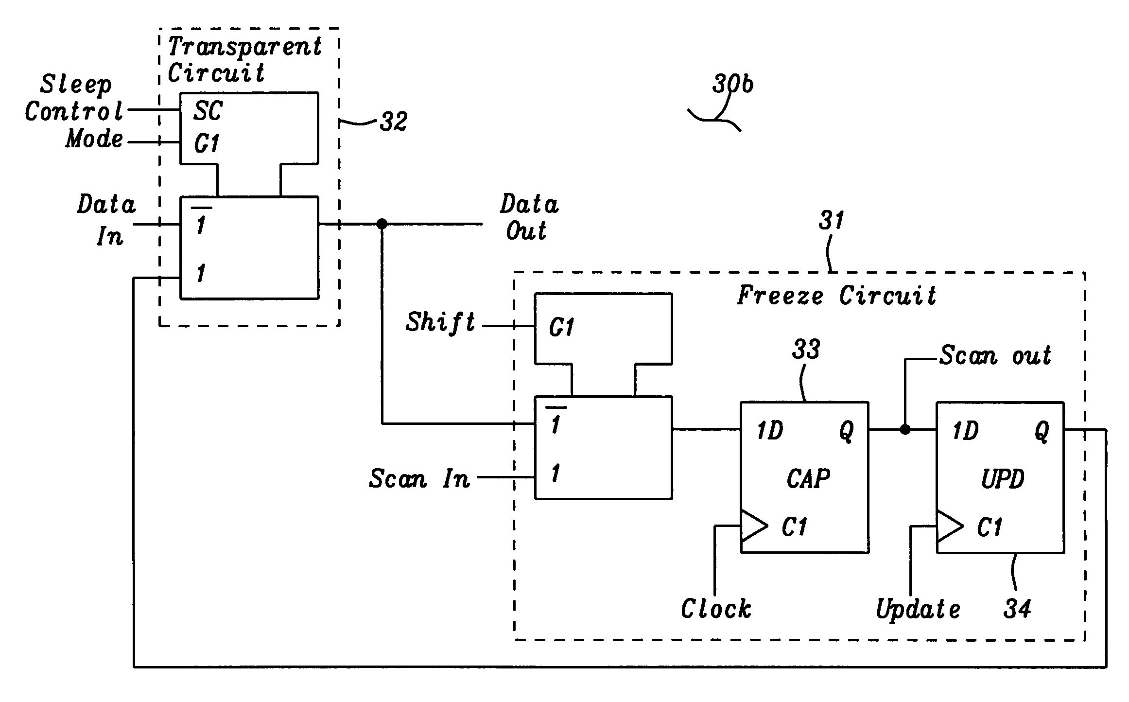
[0034]FIG. 4B is a circuit diagram 41 of first embodiment of the transparent circuit 32. When the sleep control is off, +V, the mode select signal G1 connects to two transistors, a p-channel device 42 and an n-channel device 43, which selects either input In0 (Data In) or input In1 (Scan In), to connect to the select circuits formed by the p-channel transistor 50 and the n-channel transistor 51, and the select circuit formed by the p-channel transistor 52 and the n-channel transistor 53. The output of the select circuits connect to the input of the output circuit formed by the p-channel transistor 54 and the n-channel transistor 55, where the output circuit provides an out put signal “Z”. Input I0 or I1 is selected by the application of the G1 signal from the p-channel transistor 42 to the gates of the selector circuit gates of the n-channel transistor 51 and the p-channel transistor 52 while the inverted G1 signal is applied to the selector circuit gates of the p-channel transistor...
second embodiment
[0038]When the sleep control is off, +V, in the circuit of the second embodiment, the mode select signal G1 connects to two transistors, a p-channel device 42 and an n-channel device 43, which selects either input In0 (Data In) or input In1 (Scan In). The mode select signal G1 controls the selection of the appropriate input to the select circuits formed by the p-channel transistor 50 and the n-channel transistor 51, and the select circuit formed by the p-channel transistor 52 and the n-channel transistor 53. The select circuits connect to the input of the output circuit formed by the p-channel transistor 54 and the n-channel transistor 55, where the output circuit provides an out put signal “Z”. Input I0 or I1 is selected by the application of the G1 signal from the p-channel transistor 42 to the gates of the n-channel transistor 51 and the p-channel transistor 52. At the same time an inverted G1 signal is applied to the selector circuit gates of the p-channel transistor 50 and the ...
PUM
 Abstract
Description
Claims
Application Information
 - R&D
- Intellectual Property
- Life Sciences
- Materials
- Tech Scout
- Unparalleled Data Quality
- Higher Quality Content
- 60% Fewer Hallucinations
Browse by: Latest US Patents, China's latest patents, Technical Efficacy Thesaurus, Application Domain, Technology Topic, Popular Technical Reports.
© 2025 PatSnap. All rights reserved.Legal|Privacy policy|Modern Slavery Act Transparency Statement|Sitemap|About US| Contact US: help@patsnap.com


