
Variable frequency oscillator circuits and methods of generating an oscillating signal of a desired frequency
a frequency oscillator and frequency technology, applied in the direction of oscillator, demodulation, electrical apparatus, etc., can solve the problems of reducing the performance requirement of the image-reject filter, the image rejection provided by the image-reject mixer alone is often insufficient, and the cavity filter can be very bulky and expensiv
- Summary
- Abstract
- Description
- Claims
- Application Information
AI Technical Summary
Benefits of technology
Problems solved by technology
Method used
Image

Examples
Embodiment Construction
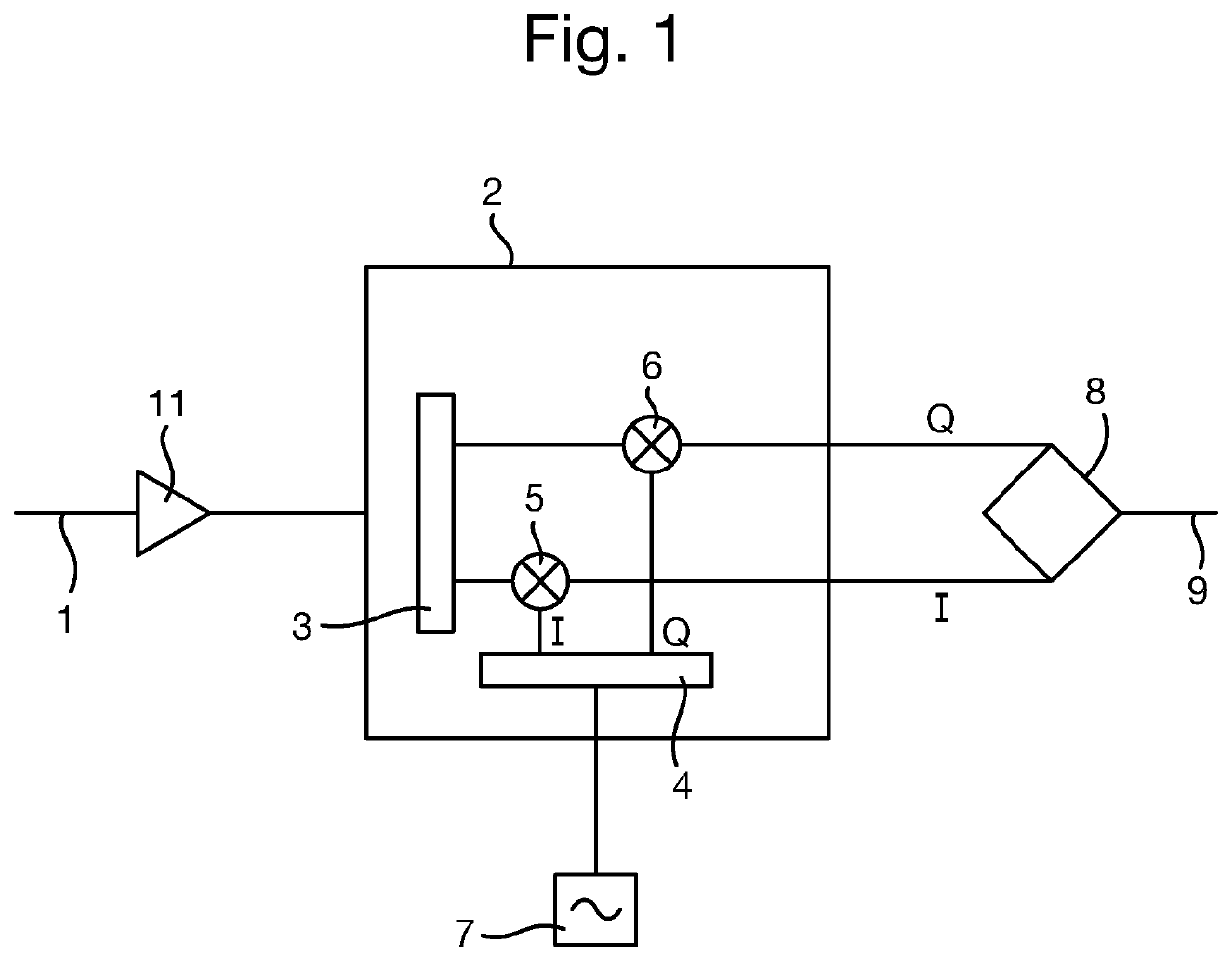
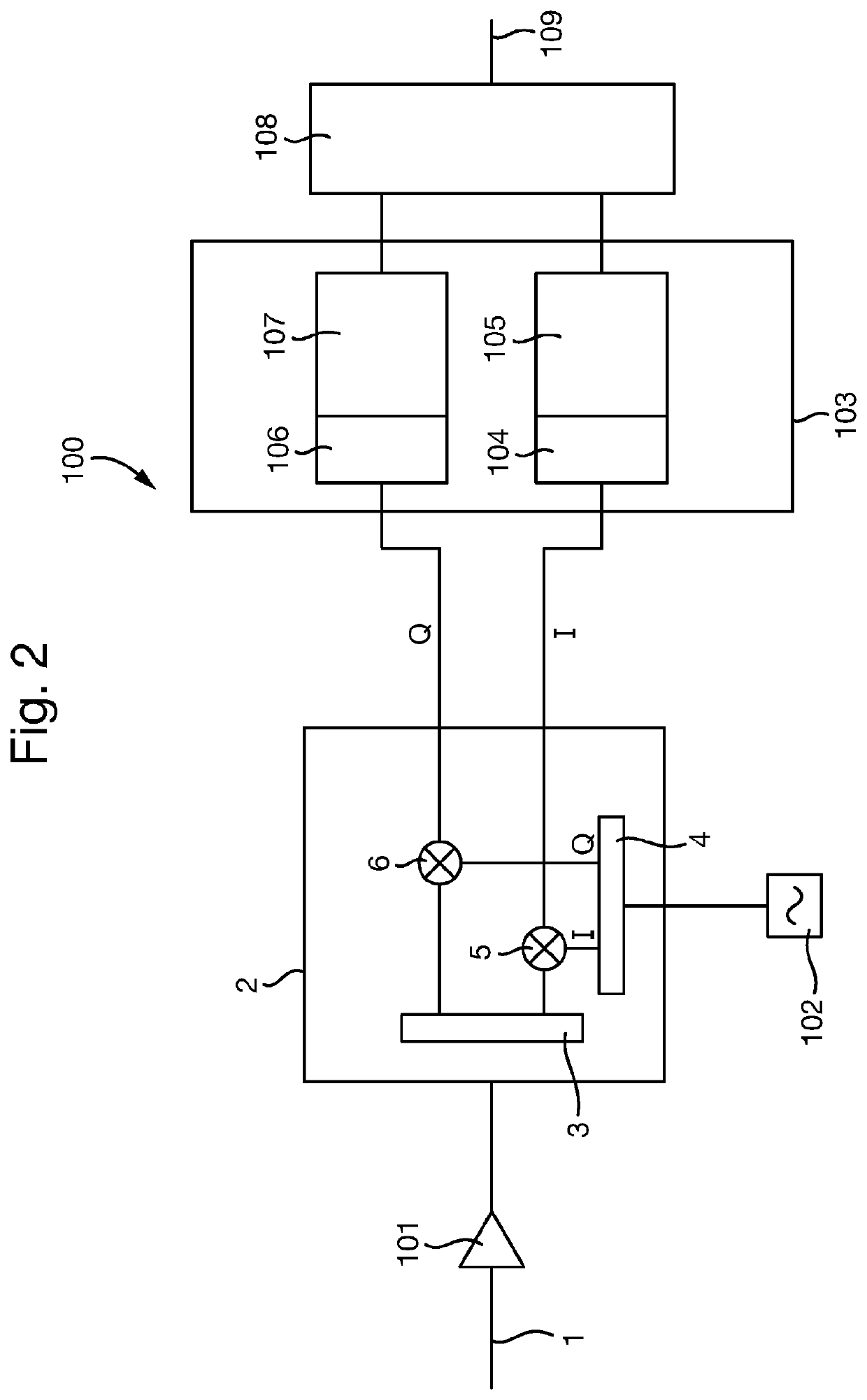
[0046]A part of a superhet receiver circuit in accordance with an embodiment of the invention is shown in FIG. 2. As in the known superhet receiver circuit 10 of FIG. 1, the superhet receiver circuit 100 receives an RF signal 1, which is amplified by an amplifier 101, as well as other desirable filtering, attenuation etc. that may be performed. The amplified signal is then passed to the same image-reject mixer 2 as in the known superhet receiver circuit 10, again comprising a signal splitter 3, quadrature splitter 4 and frequency mixers 5 and 6. The image-reject mixer 2 also receives the output of a variable frequency oscillator 102, which is described in more detail later below.
[0047]The in-phase and quadrature signals output by the image-reject mixer 2 are then passed to a multiple-input and multiple-output (MIMO) integrated circuit 103. MIMOs are designed for use in integrated radio transceivers that use multiple antennas, and as such conveniently have multiple channels that tune...
PUM
 Abstract
Description
Claims
Application Information