MEMS element and oscillator

a technology of oscillator and element, applied in the direction of oscillator, piezoelectric/electrostrictive/magnetostrictive device, semiconductor device, etc., can solve the problems of vibration oscillation in an oscillation, and the oscillation is likely to occur at an unintended frequency, and achieve the effect of stable characteristics

Inactive Publication Date: 2014-04-03
SEIKO EPSON CORP
View PDF11 Cites 0 Cited by
  • Summary
  • Abstract
  • Description
  • Claims
  • Application Information

AI Technical Summary

Benefits of technology

[0008]An advantage of some aspects of the invention is to provide a MEMS element in which other vibration modes can be distanced from the first vibration mode and which can be oscillated at a desired frequency. Moreover, another advantage of some aspects of the invention is to provide an oscillator including the MEMS element.
[0017]According to the MEMS element of this configuration, differences in frequency between the first vibration mode and the other vibration modes can be further increased. That is, the other vibration modes can be further distanced from the first vibration mode.
[0019]According to the oscillator, since the MEMS element according to the aspect of the invention is included, stable characteristics can be provided.

Problems solved by technology

For example, in the case of using the first vibration mode as an oscillator, when a difference between a frequency of the first vibration mode and a frequency (spurious) of the second vibration mode is small as shown in FIG. 14, there is a problem in that the vibrator oscillates in an oscillation condition satisfied by the second vibration mode.
Therefore, oscillation is likely to occur at an unintended frequency.

Method used


Image

  • MEMS element and oscillator
  • MEMS element and oscillator
  • MEMS element and oscillator

Examples


first embodiment

1. First Embodiment

1.1. MEMS Element

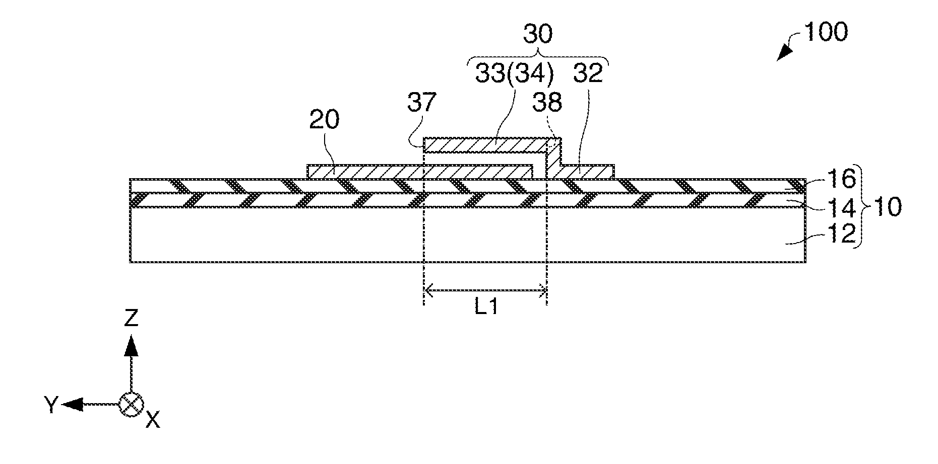
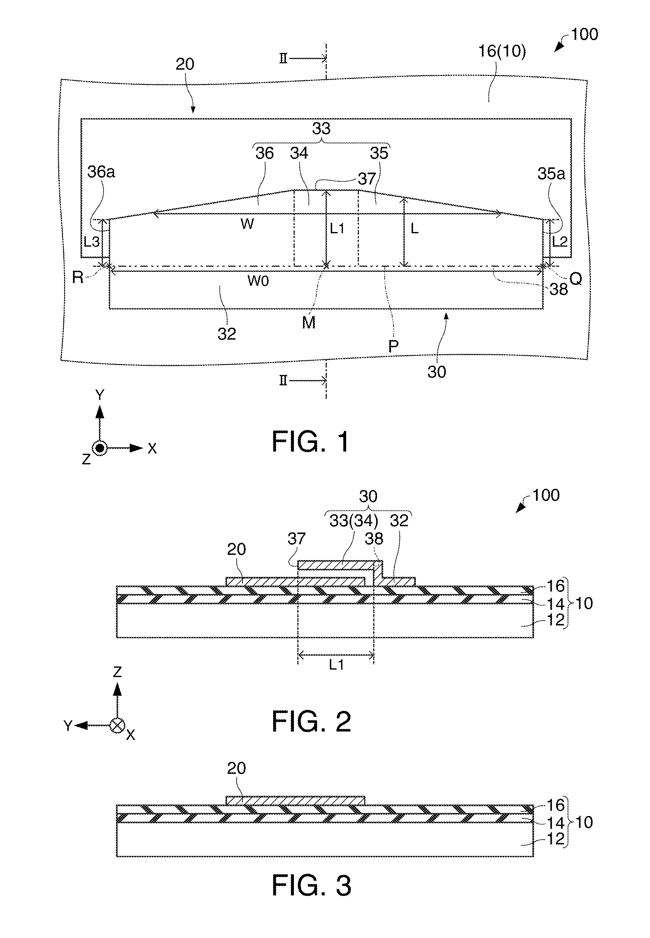
[0036]First, a MEMS element according to a first embodiment will be described with reference to the drawings. FIG. 1 is a plan view schematically showing the MEMS element 100 according to the first embodiment. FIG. 2 is a cross-sectional view schematically showing the MEMS element 100 according to the first embodiment taken along line II-II in FIG. 1. In FIGS. 1 and 2, an X-axis, a Y-axis, and a Z-axis are shown as three axes perpendicular to each other.

[0037]Hereinafter, the MEMS element 100 will be described as a MEMS vibrator.

[0038]As shown in FIGS. 1 and 2, the MEMS element 100 includes a substrate 10, a first electrode 20, and a second electrode 30. The substrate 10 has a support substrate 12, a first under layer 14, and a second under layer 16.

[0039]As the support substrate 12, a semiconductor substrate such as a silicon substrate, for example, is used. As the support substrate 12, various types of substrates such as a ceramics substrate, a ...

second embodiment

2. Second Embodiment

2.1. MEMS Element

[0082]Next, a MEMS element according to a second embodiment will be described with reference to the drawings. FIG. 9 is a plan view schematically showing the MEMS element 200 according to the second embodiment. In FIG. 9, the X-axis, the Y-axis, and the Z-axis are shown as three axes perpendicular to each other. In the MEMS element 200 according to the second embodiment described below, members having a similar function to that of the constituent member of the MEMS element 100 according to the first embodiment are denoted by the same reference numeral and sign, and the detailed description thereof is omitted.

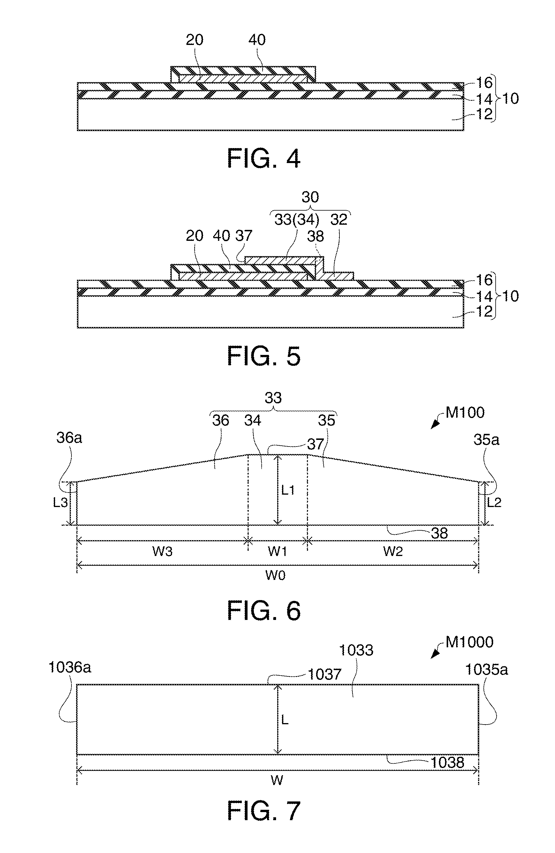
[0083]In the MEMS element 100 as shown in FIG. 1, the beam portion 33 has the first part 34 of a rectangular shape in plan view and the second parts 35 and 36 of a trapezoidal shape in plan view. In contrast to this, in the MEMS element 200, the beam portion 33 has an arc shape in plan view as shown in FIG. 9.

[0084]In the MEMS element 200, th...

third embodiment

3. Third Embodiment

[0094]Next, an oscillator according to a third embodiment will be described with reference to the drawings. FIG. 12 is a circuit diagram showing the oscillator 300 according to the third embodiment.

[0095]As shown in FIG. 12, the oscillator 300 includes, for example, the MEMS element (for example, the MEMS element 100 as a MEMS vibrator) according to the embodiment of the invention and an inverting amplifier circuit (circuit portion) 310.

[0096]The MEMS element 100 has a first terminal 100a electrically connected with the first electrode 20 and a second terminal 100b electrically connected with the second electrode 30. The first terminal 100a of the MEMS element 100 is at least AC-connected with an output terminal 310b of the inverting amplifier circuit 310. The second terminal 100b of the MEMS element 100 is at least AC-connected with an input terminal 310a of the inverting amplifier circuit 310.

[0097]In the illustrated example, the inverting amplifier circuit 310 ...


PUM


Abstract

A MEMS element includes: a substrate; a first electrode formed above the substrate; and a second electrode having a support portion and a beam portion, the support portion being formed above the substrate, the beam portion extending from the support portion, being formed in a state of having a gap between the first electrode and the beam portion, and being capable of vibrating in a thickness direction of the substrate. The width of the beam portion decreases with distance from a base of the beam portion toward a tip of the beam portion. The central length of the beam portion is larger than the lengths of ends of the beam portion. The width of the base of the beam portion is larger than the central length of the beam portion.

Description

BACKGROUND[0001]1. Technical Field[0002]The present invention relates to a MEMS element and an oscillator.[0003]2. Related Art[0004]MEMS (micro electro mechanical systems), which are one of techniques for forming a minute structure, mean a technique for making a micro electro mechanical system on the order of microns, or the product thereof, for example.[0005]For example, U.S. Patent Application Publication No. 2007 / 0279140 discloses, as a MEMS element, a MEMS vibrator including a first electrode and a second electrode having a beam portion arranged with a gap between the first electrode and the beam portion. The MEMS vibrator disclosed in U.S. Patent Application Publication No. 2007 / 0279140 is a cantilever-like vibrator in which one end of the beam portion is fixed and the beam portion has a shape whose size in its width direction is larger than in its extension direction. By making the beam portion large in the width direction in this manner, an electrostatic force between the bea...

Claims


Application Information

Patent Timeline
Patent Type & Authority Applications(United States)
IPC IPC(8): B81B3/00
CPCB81B3/0021H03H9/2457H03H2009/02251H03H2009/02488H03B5/30H03H2009/02511B81B2201/0271B81B2203/019B81B2203/0118
Inventor KIHARA, RYUJI
Owner SEIKO EPSON CORP
Why Eureka
Try Eureka