
Variable frequency oscillator circuits and methods of generating an oscillating signal of a desired frequency

a frequency oscillator and frequency technology, applied in the direction of oscillator, demodulation, electrical apparatus, etc., can solve the problems of reducing the performance requirement of the image-reject filter, the image rejection provided by the image-reject mixer alone is often insufficient, and the cavity filter can be very bulky and expensiv

Active Publication Date: 2020-03-12
BAE SYSTEMS PLC
View PDF2 Cites 0 Cited by
  • Summary
  • Abstract
  • Description
  • Claims
  • Application Information

AI Technical Summary

Benefits of technology

The patent describes a circuit that uses a fixed frequency oscillator to generate an oscillating signal at a desired frequency. This circuit can also suppress unwanted signals at other frequencies using a receiver to monitor the generated signal. Additionally, the circuit can modify the operation of the mixer to suppress unwanted signals by adjusting the DC levels, amplitude, and phase of the received signals. Overall, this patent provides a cost-effective and reliable method to generate oscillating signals with minimal unwanted signals.

Problems solved by technology

The degree of image rejection provided by an image-reject mixer alone is often insufficient, due to imbalances within the image-reject mixer and quadrature components, but an image-reject mixer can reduce the performance requirement of the image-reject filter.
However, cavity filters can be very bulky and expensive.
Another problem with superhet receiver circuits, particularly (but not exclusively) when operating at microwave frequencies, is that a low phase noise variable frequency oscillator can be difficult to provide.
This means that variable frequency oscillator may suffer from short-term frequency movement affecting the performance of the receiver.
Variable frequency oscillators that do not suffer from these disadvantages can be bulky and / or expensive.

Method used


Image

  • Variable frequency oscillator circuits and methods of generating an oscillating signal of a desired frequency
  • Variable frequency oscillator circuits and methods of generating an oscillating signal of a desired frequency
  • Variable frequency oscillator circuits and methods of generating an oscillating signal of a desired frequency

Examples


Embodiment Construction

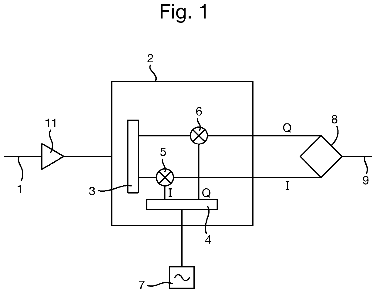
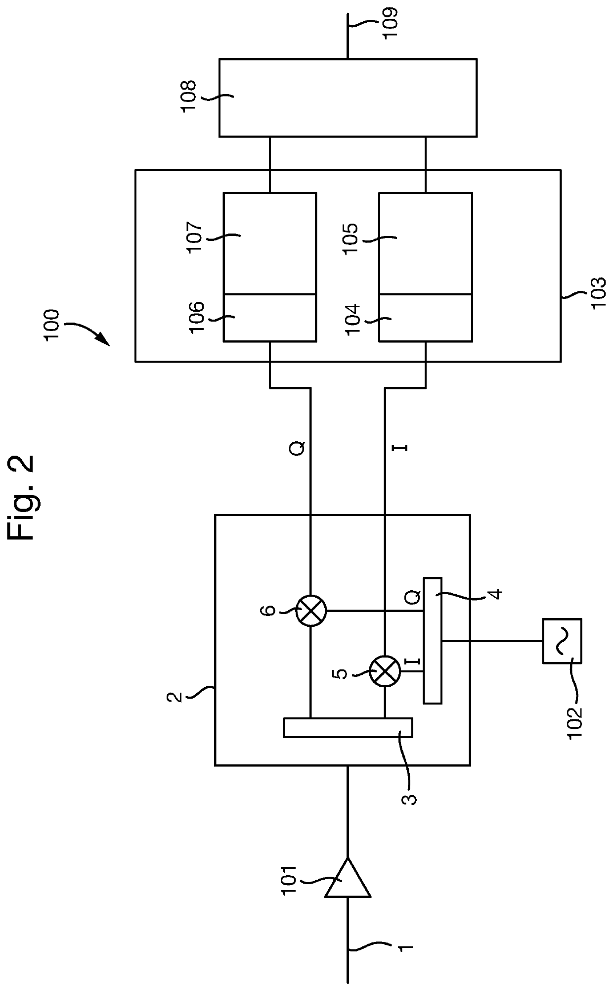
[0046]A part of a superhet receiver circuit in accordance with an embodiment of the invention is shown in FIG. 2. As in the known superhet receiver circuit 10 of FIG. 1, the superhet receiver circuit 100 receives an RF signal 1, which is amplified by an amplifier 101, as well as other desirable filtering, attenuation etc. that may be performed. The amplified signal is then passed to the same image-reject mixer 2 as in the known superhet receiver circuit 10, again comprising a signal splitter 3, quadrature splitter 4 and frequency mixers 5 and 6. The image-reject mixer 2 also receives the output of a variable frequency oscillator 102, which is described in more detail later below.

[0047]The in-phase and quadrature signals output by the image-reject mixer 2 are then passed to a multiple-input and multiple-output (MIMO) integrated circuit 103. MIMOs are designed for use in integrated radio transceivers that use multiple antennas, and as such conveniently have multiple channels that tune...


PUM


Abstract

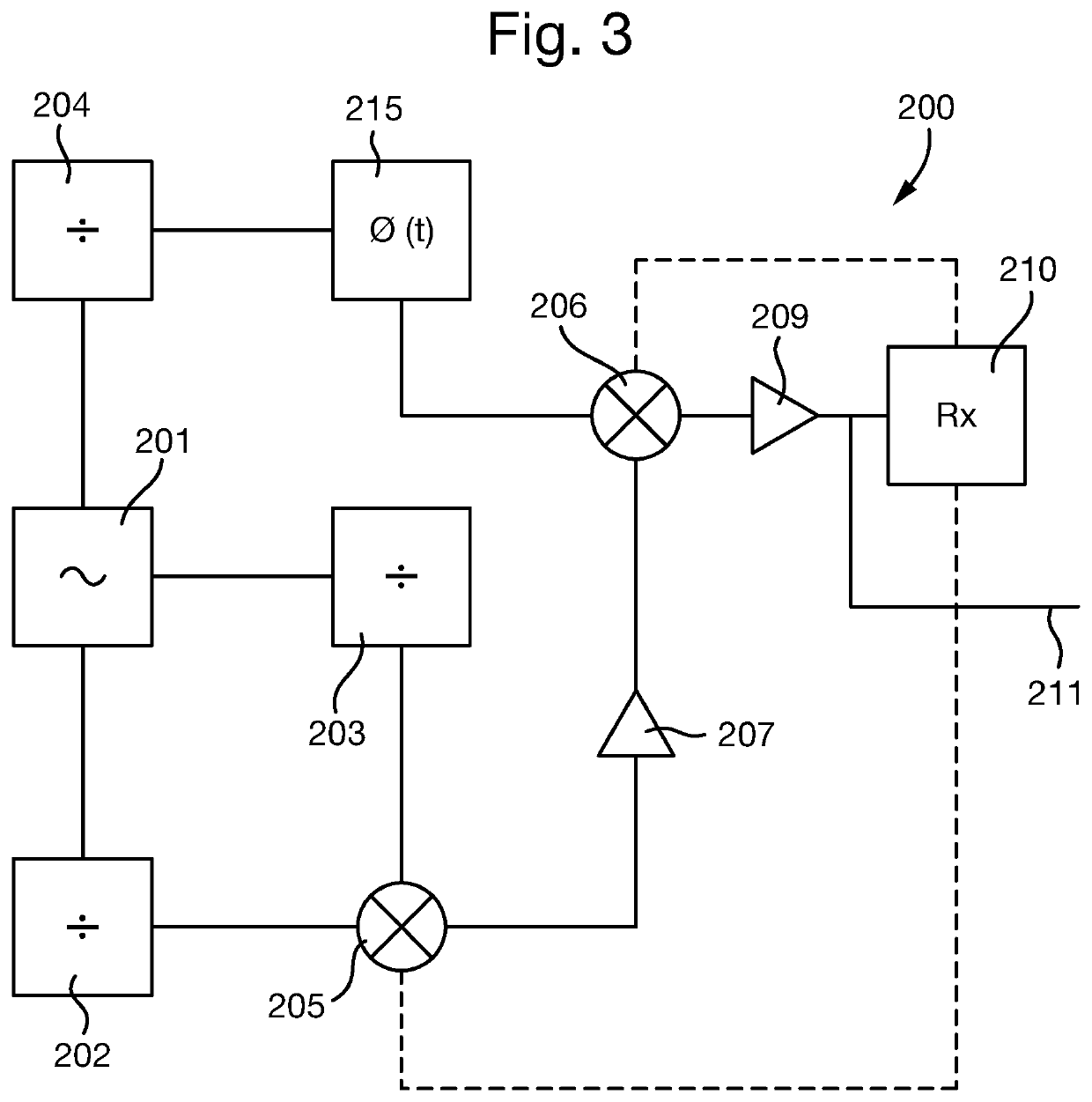
A variable frequency oscillator circuit for generating an oscillating signal of a desired frequency, comprising a fixed frequency oscillator; one or more frequency dividers, arranged to receive the output of the fixed frequency oscillator and generate a signal with a divided frequency; and one or mixers, arranged to mix the outputs of the one or more frequency dividers to generate the oscillating signal of the desired frequency. The variable frequency oscillator circuit is arranged to modify the operation of the one or more mixers to suppress any unwanted signals in the generated oscillating signal.

Description

FIELD OF THE INVENTION[0001]The present invention concerns variable frequency oscillator circuits and methods of generating an oscillating signal of a desired frequency. More particularly, but not exclusively, the invention concerns superheterodyne radio receiver circuits operating at microwave and ultrahigh frequencies.BACKGROUND OF THE INVENTION[0002]Superheterodyne (“superhet”) is a well-established radio receiver architecture. A superhet receiver circuit uses frequency mixing with a local oscillator (LO) to convert a received radio signal to an intermediate frequency (IF) ahead of further signal processing. However, it is a feature of superhet receiver circuits that during conversion of the received radio signal, as well as the desired signal, signals originating from an “image” frequency can be present.[0003]If the desired signal is at a frequency that is the sum of the IF frequency and the LO frequency, then the image frequency is the difference between LO and IF frequencies. ...

Claims


Application Information

Patent Timeline
IPC IPC(8): H03B1/04H03D7/16H03D7/18H03B21/01H03B19/14
CPCH03D7/18H03B21/01H03B19/14H03D7/16H03B1/04H03D7/165
Inventor PRING, PHILIP CHARLES JARRETT
Owner BAE SYSTEMS PLC
Learn More