Capacitor-compensation-type generator

a generator and capacitor technology, applied in the direction of electrical generator control, control system, electrical apparatus, etc., can solve the problems of insufficient type of generator in this regard, inability to provide stable output voltage,

Active Publication Date: 2012-01-31
HONDA MOTOR CO LTD
View PDF8 Cites 0 Cited by
  • Summary
  • Abstract
  • Description
  • Claims
  • Application Information

AI Technical Summary

Benefits of technology

[0009]In order to achieve the object, this invention provides, in a second aspect, a method of controlling a capacitor-compensation-type generator having a rotor wound with a field winding that is short-circuited with a diode, a stator wound with an output winding that is adapted to cross flux generated by the field winding to output AC power and with an exciting winding that is disposed at predetermined phase angle with respect to the output winding and is short-circuited with a phase advance capacitor, an internal combustion engine that drives the rotor to rotate relative to the stator and an actuator that changes the engine speed, comprising the steps of: detecting a speed of the engine; detecting output voltage of the AC power outputted from the output winding; and controlling operation of the actuator in accordance with one of a constant voltage operation mode in which the detected engine speed is controlled to a desired speed such that the detected output voltage becomes a desired voltage, and a constant frequency operation mode in which the detected engine speed is controlled to a predetermined speed such that frequency of AC power outputted from the output winding becomes a desired frequency.
[0054]Specifically, in the case of the constant voltage operation mode, the AC power at constant voltage which is required by the user can be outputted regardless of increase or decrease in load, and in the case of the constant frequency operation mode, the AC power at constant frequency can be outputted regardless of variation in load. Further, the engine speed NE is controlled to be low under low load in the constant voltage operation mode, thereby enhancing fuel efficiency and improving environmental friendliness due to lowered noise level.
[0009]In order to achieve the object, this invention provides, in a second aspect, a method of controlling a capacitor-compensation-type generator having a rotor wound with a field winding that is short-circuited with a diode, a stator wound with an output winding that is adapted to cross flux generated by the field winding to output AC power and with an exciting winding that is disposed at predetermined phase angle with respect to the output winding and is short-circuited with a phase advance capacitor, an internal combustion engine that drives the rotor to rotate relative to the stator and an actuator that changes the engine speed, comprising the steps of: detecting a speed of the engine; detecting output voltage of the AC power outputted from the output winding; and controlling operation of the actuator in accordance with one of a constant voltage operation mode in which the detected engine speed is controlled to a desired speed such that the detected output voltage becomes a desired voltage, and a constant frequency operation mode in which the detected engine speed is controlled to a predetermined speed such that frequency of AC power outputted from the output winding becomes a desired frequency.
[0007]An object of this invention is therefore to overcome the foregoing problem by providing a capacitor-compensation-type generator or method of controlling the same that can output AC power at constant voltage or frequency.
[0014]FIG. 4 is an explanatory graph showing characteristics of a constant voltage operation mode and a constant frequency operation mode conducted by the ECU shown in FIG. 1;

Problems solved by technology

However, the output voltage increases with increasing speed of the engine and fluctuates in response to increase or decrease in load, disadvantageously resulting in unstable output voltage.
Also, it is preferable for a certain load that frequency is constant, but this type of generator is not necessarily satisfactory in this regard.

Method used


Image

  • Capacitor-compensation-type generator
  • Capacitor-compensation-type generator
  • Capacitor-compensation-type generator

Examples


Embodiment Construction

[0017]A capacitor-compensation-type generator according to a preferred embodiment of the present invention will now be explained with reference to the attached drawings.

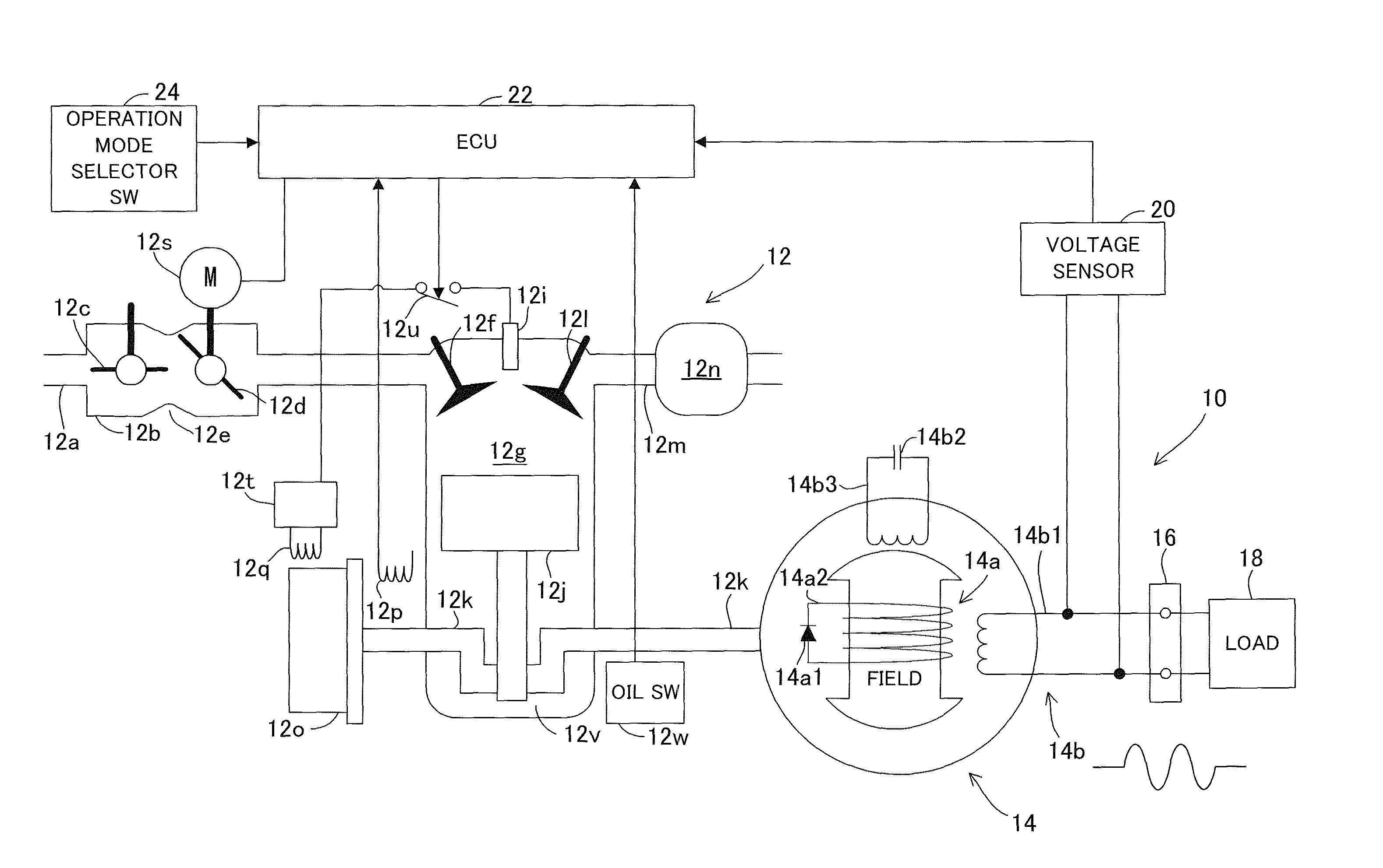
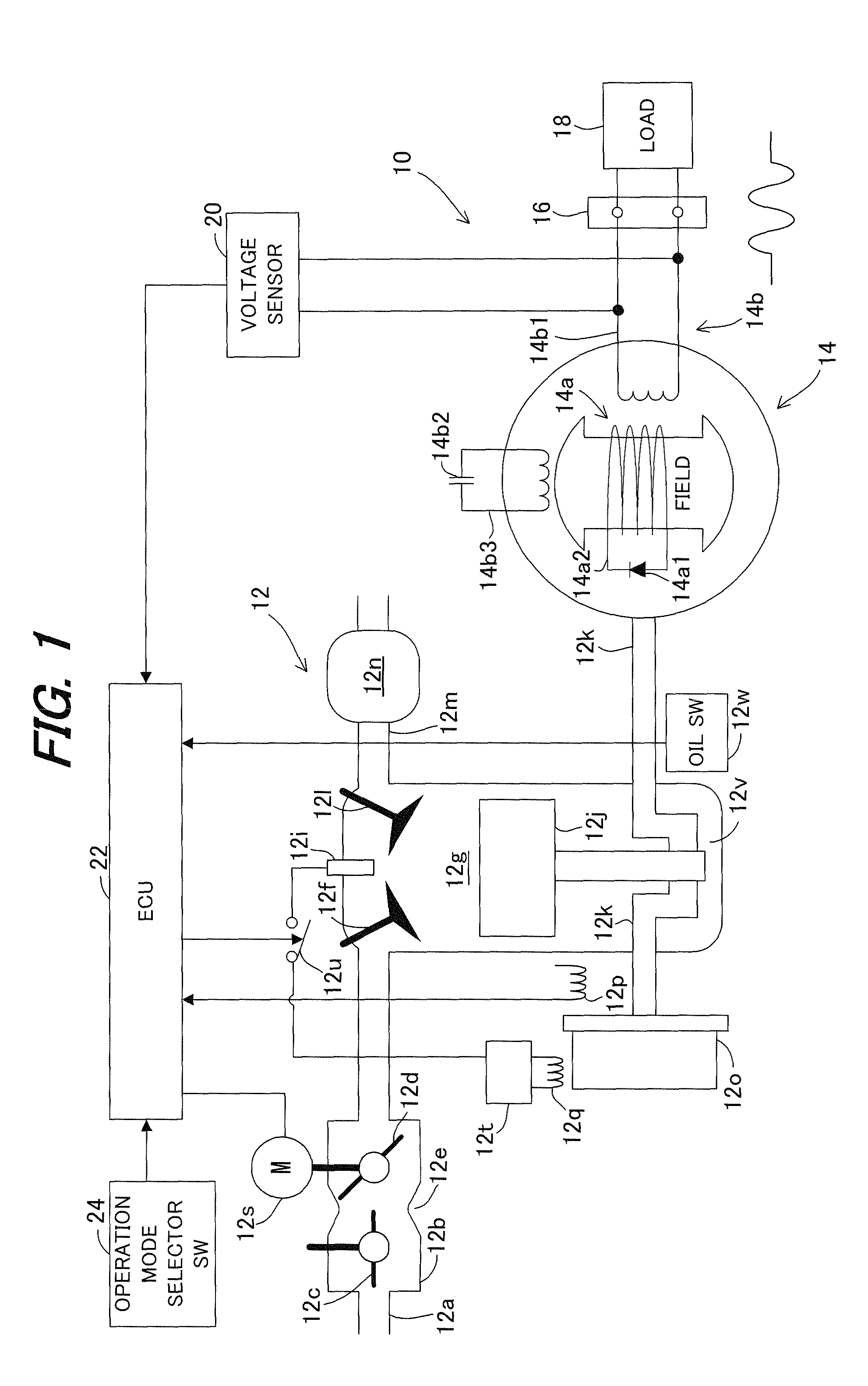
[0018]FIG. 1 is a block diagram entirely showing a capacitor-compensation-type generator according to an embodiment of the invention.

[0019]In FIG. 1, reference numeral 10 designates the capacitor-compensation-type generator that is equipped with an internal combustion engine (hereinafter called “engine”; ENG) 12 and has a rated output of AC 100V-2.1 kVA. The generator 10 is originally a brushless single-phase synchronous generator.

[0020]The engine 12 is an air-cooled, spark-ignition engine that runs on gasoline. Air sucked in through an air cleaner (not shown) flows through an intake pipe 12a and carburetor 12b. A choke valve 12c and throttle valve 12d are installed in the carburetor 12b to regulate the intake air.

[0021]The gasoline fuel pumped from a fuel tank (not shown) is injected through a venturi 12e to be mixe...


PUM


Abstract

In a capacitor-compensation-type generator having a rotor wound with a field winding, a stator wound with an output winding adapted to cross flux generated by the field winding to output AC power, and an internal combustion engine that drives the rotor to rotate relative to the stator, there are equipped with an actuator that changes the engine speed and an actuator controller that controls operation of the actuator in accordance with a constant voltage operation mode in which the engine speed is controlled to a desired speed such that a detected output voltage becomes a desired voltage, or a constant frequency operation mode in which the detected engine speed is controlled to a predetermined speed such that frequency of AC power outputted from the output winding becomes a desired frequency, thereby enabling to output AC power at constant voltage or frequency.

Description

BACKGROUND OF THE INVENTION[0001]1. Field of the Invention[0002]This invention relates to a capacitor-compensation-type generator and a method for controlling the same.[0003]2. Description of the Related Art[0004]There is known a capacitor-compensation-type generator having a rotor wound with a field winding that is short-circuited with a diode, a stator wound with an output winding that is adapted to cross the flux generated by the field winding to produce AC power and with an exciting winding that is disposed at predetermined phase angle with respect to the output winding and is short-circuited with a phase advance capacitor, and an internal combustion engine for driving the rotor relative to the stator, as taught, for example, in Japanese Laid-Open Patent Application No. Sho 63 (1988)-227960. The generator of this type is originally a brushless single-phase synchronous generator that is also called “Nonaka-type generator”, named after the inventor thereof.[0005]In this type of ge...

Claims


Application Information

Patent Timeline
Patent Type & Authority Patents(United States)
IPC IPC(8): H02P9/04
CPCH02P9/04H02P9/302H02P9/48
Inventor KAMIMURA, KENJISHIMIZU, MOTOHIRO
Owner HONDA MOTOR CO LTD
Why Eureka
Try Eureka