Coherent detection without transmission preamble

Inactive Publication Date: 2008-04-24
COMTECH MOBILE DATACOM CORP
View PDF4 Cites 72 Cited by
  • Summary
  • Abstract
  • Description
  • Claims
  • Application Information

AI Technical Summary

Benefits of technology

[0009] Conventionally, communication messages (whether spread-spectrum or not) include a ‘preamble’ (also known as a ‘front porch’) that is prepended to the information content of the message to facilitate all necessary synchronization of the receiver to the transmitted signal and other required functions, such as identifying the beginning of each message, identifying bit polarity, aligning data packets, and so on. However, in the above referenced applications, the transmitters are often required to be portable and battery-operated. In applications where the information content is small, such as a report of the security of a lock on a transport container, the transmission of the preamble with each short message often consumes more energy than the transmission of the information. It also occupies a disproportionate amount of total system bandwidth, reducing the maximum number of possible users in the system: time spent transmitting non-information-containing preamble bits is time another device cannot spend transmitting useful data. In an information theory sense, the most useful communication is a highly stochastic bit sequence, yet the purpose of a preamble is to be a completely nonstochastic (predictable) bit sequence.
[0010] It would be advantageous to provide a receiving system that is configured to distinguish among transmissions from a plurality of transmitters that share a communication channel and use a common DSS

Problems solved by technology

The modulated signal is spread across a bandwidth that is substantially larger than the bandwidth of the information signal, and has the apparent effect of increasing the noise-floor of receivers that receive this signal.
The requirement to dedicate a receiver to each active transmitter requires the use of multiple receivers operating in parallel, which can become costly, particularly if the receiving system needs to be designed for a ‘peak’ number of simultaneously transmitting transmitters.
In ap

Method used


Image

  • Coherent detection without transmission preamble
  • Coherent detection without transmission preamble
  • Coherent detection without transmission preamble

Examples


Embodiment Construction

[0018] In the following description, for purposes of explanation rather than limitation, specific details are set forth such as the particular architecture, interfaces, techniques, etc., in order to provide a thorough understanding of the concepts of the invention. However, it will be apparent to those skilled in the art that the present invention may be practiced in other embodiments, which depart from these specific details. In like manner, the text of this description is directed to the example embodiments as illustrated in the Figures, and is not intended to limit the claimed invention beyond the limits expressly included in the claims. For purposes of simplicity and clarity, detailed descriptions of well-known devices, circuits, and methods are omitted so as not to obscure the description of the present invention with unnecessary detail.

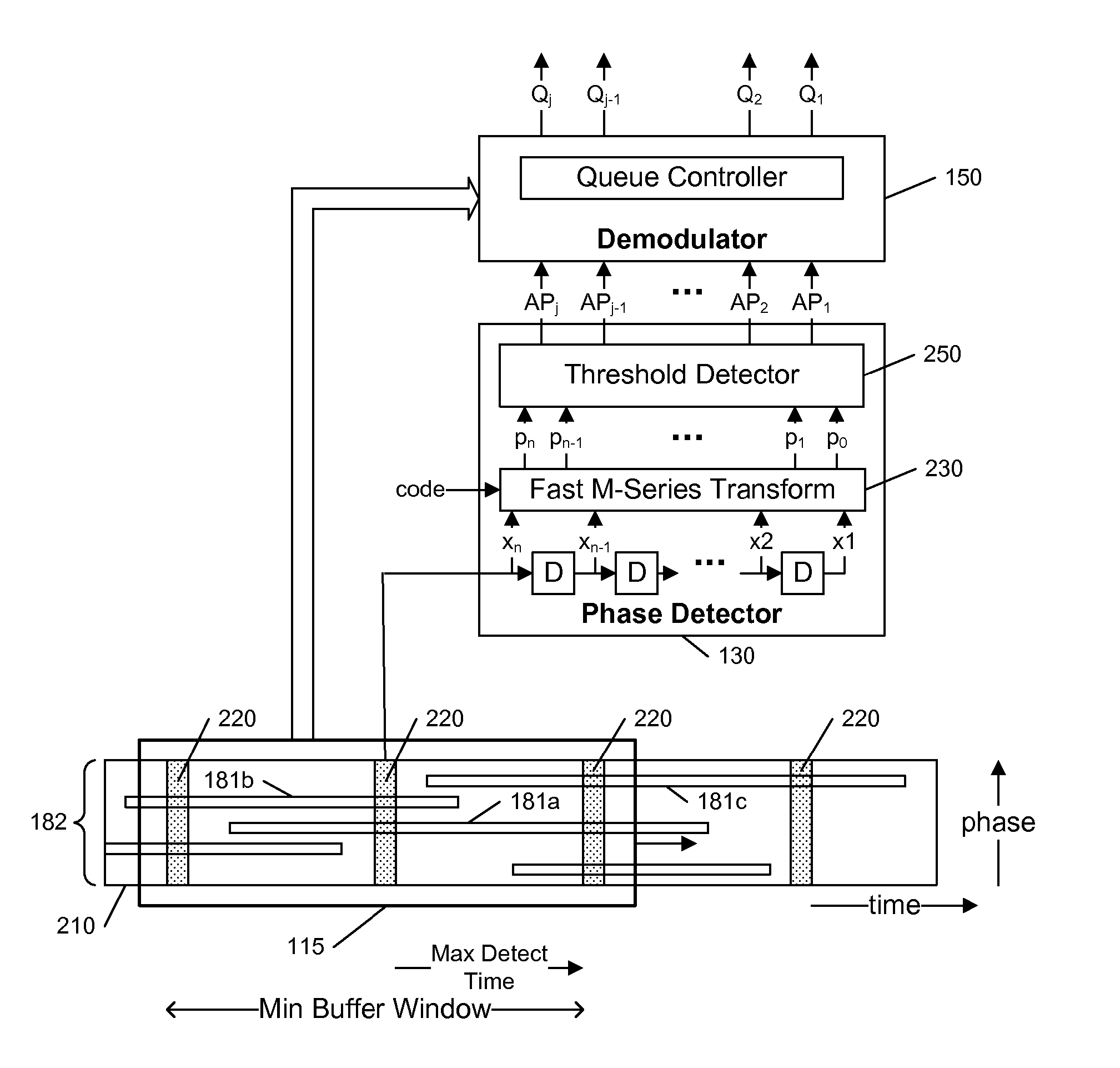
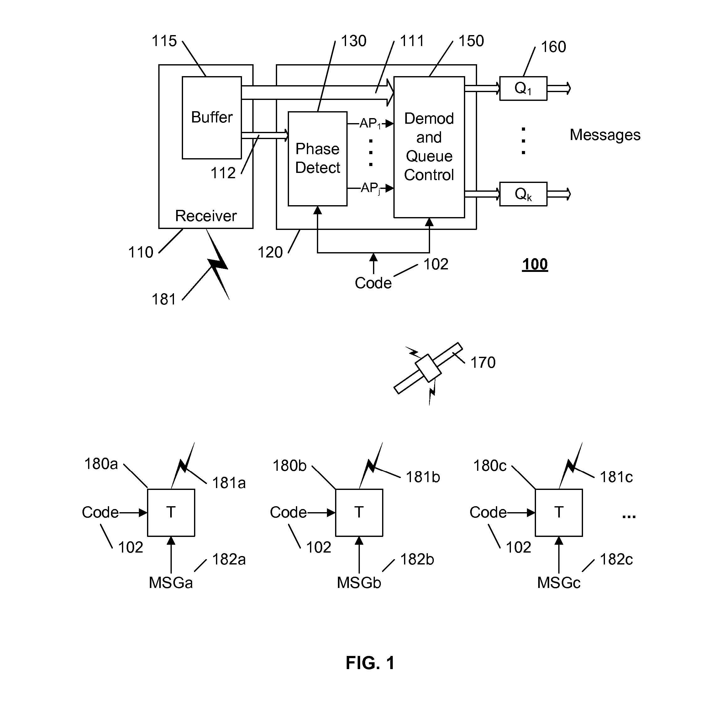
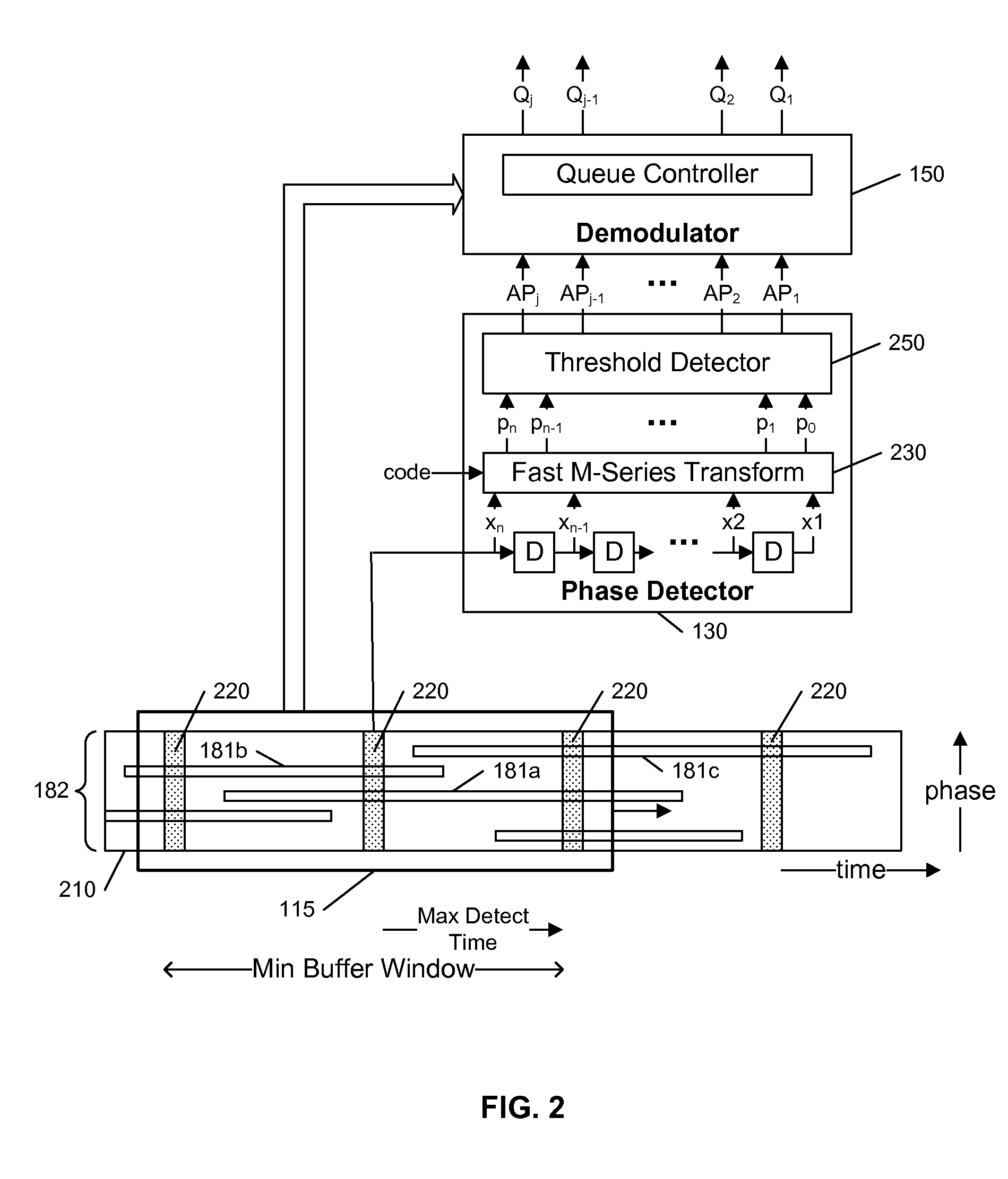
[0019]FIG. 1 illustrates an example block diagram of a communications system 100 in accordance with this invention. The communications system ...


PUM


Abstract

A receiving system allows for the coherent detection of a spread-spectrum transmission at any point in time during the transmission, thereby avoiding the need to identify the start of the transmission during the transmission-detection process. An input buffer captures the transmissions on a communication channel using a moving time-window. A detector processes a time-slice from the input buffer and identifies all of the simultaneously transmitting transmitters during that time-slice. As each transmitter is identified, the demodulator traces back-in-time to identify where the message can first be detected in the input buffer. The transmission includes suitable characteristics to facilitate detection and demodulation of the message content, but need not contain a preamble to allow the detection process.

Description

[0001] This is a continuation-in-part of U.S. patent application Ser. No. 11 / 681,759, filed 3 Mar. 2007, which is a continuation-in-part of U.S. patent application Ser. No. 10 / 208,882, filed 31 Jul. 2002, which is a continuation-in-part of U.S. Pat. No. 6,985,512, filed 28 Feb. 2000 and issued 10 Jan. 2006, each of which are incorporated by reference herein. This application also claims the benefit of U.S. Provisional Patent applications 60 / 853,735 filed 23 Oct. 2006, and 60 / 859,833, filed 17 Nov. 2006.BACKGROUND AND SUMMARY OF THE INVENTION [0002] This invention relates to the field of communications, and in particular to the processing of multiple asynchronous spread-spectrum communications. [0003] Spread-Spectrum techniques are used to modulate an information signal such that the modulated signal appears as noise. The information is modulated by a pseudo-random sequence of bits, and can be demodulated, or despread, using the same pseudo-random sequence. This modulation is commonl...

Claims


Application Information

Patent Timeline
IPC IPC(8): H04B1/707
CPCH04B1/70735H04B2001/70935H04B1/70752
Inventor MCDERMOTT, SCOTT A.STAFFORD, JAMES F.JORDAN, LUIS G.
Owner COMTECH MOBILE DATACOM CORP
Why Eureka
Try Eureka