System and method for distributing auto-attendant across user endpoints

a technology of user endpoints and auto-attendants, applied in the field of system and, can solve the problems of increased system cost and complexity, lack of redundancy,

Active Publication Date: 2008-04-24
CISCO TECH INC
View PDF11 Cites 0 Cited by
  • Summary
  • Abstract
  • Description
  • Claims
  • Application Information

AI Technical Summary

Problems solved by technology

One disadvantage is that an additional server 140 for the auto-attendant service

Method used


Image

  • System and method for distributing auto-attendant across user endpoints
  • System and method for distributing auto-attendant across user endpoints
  • System and method for distributing auto-attendant across user endpoints

Examples


Embodiment Construction

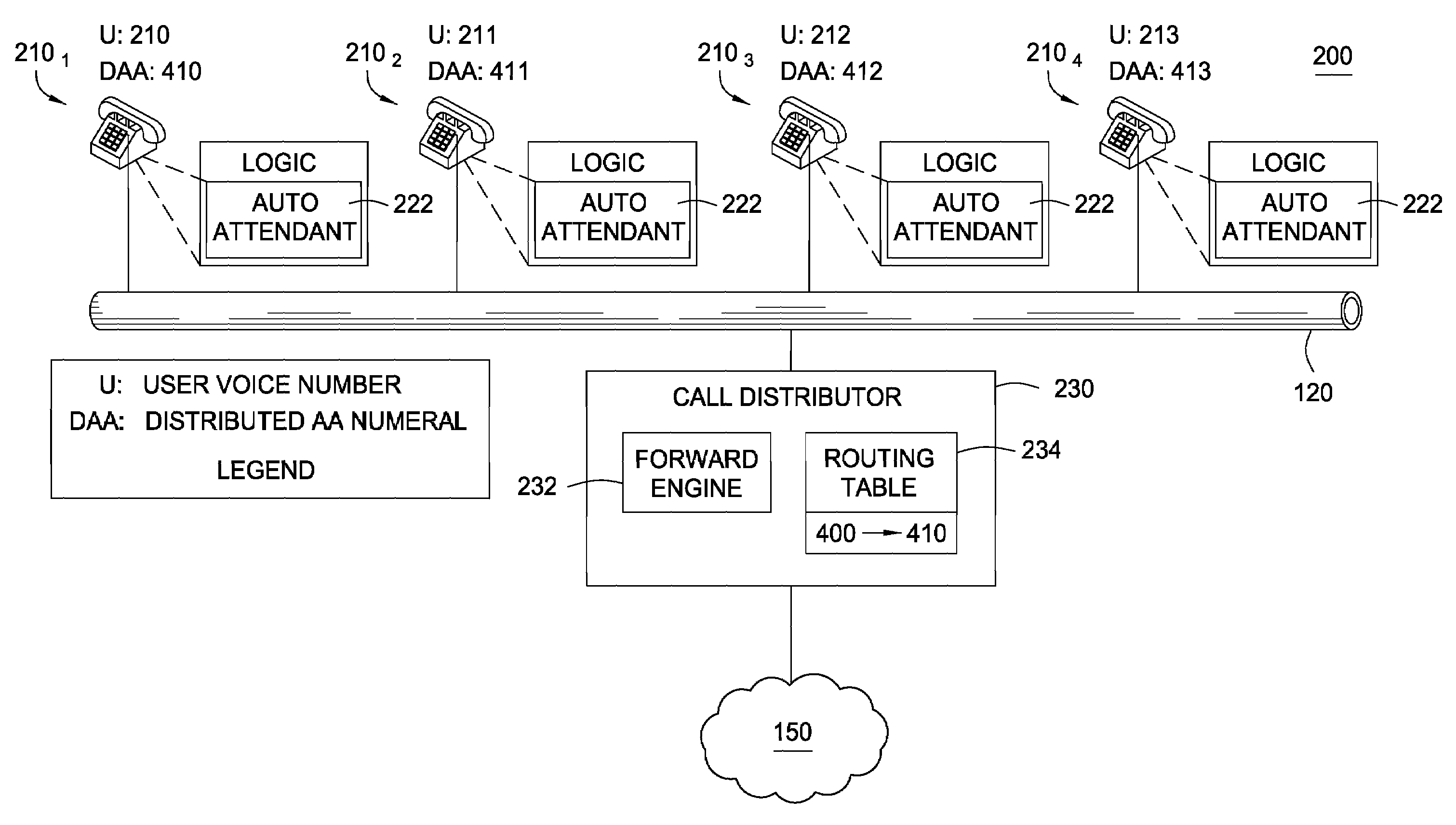
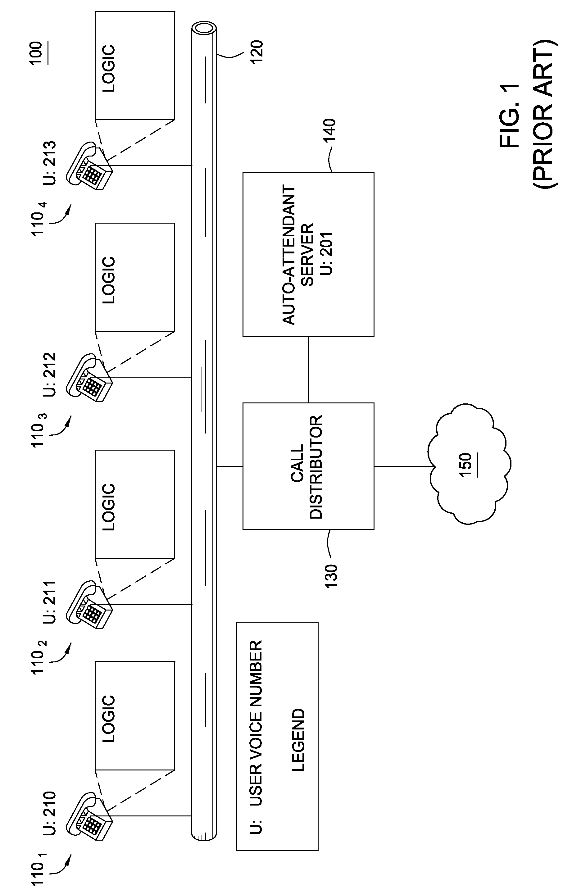
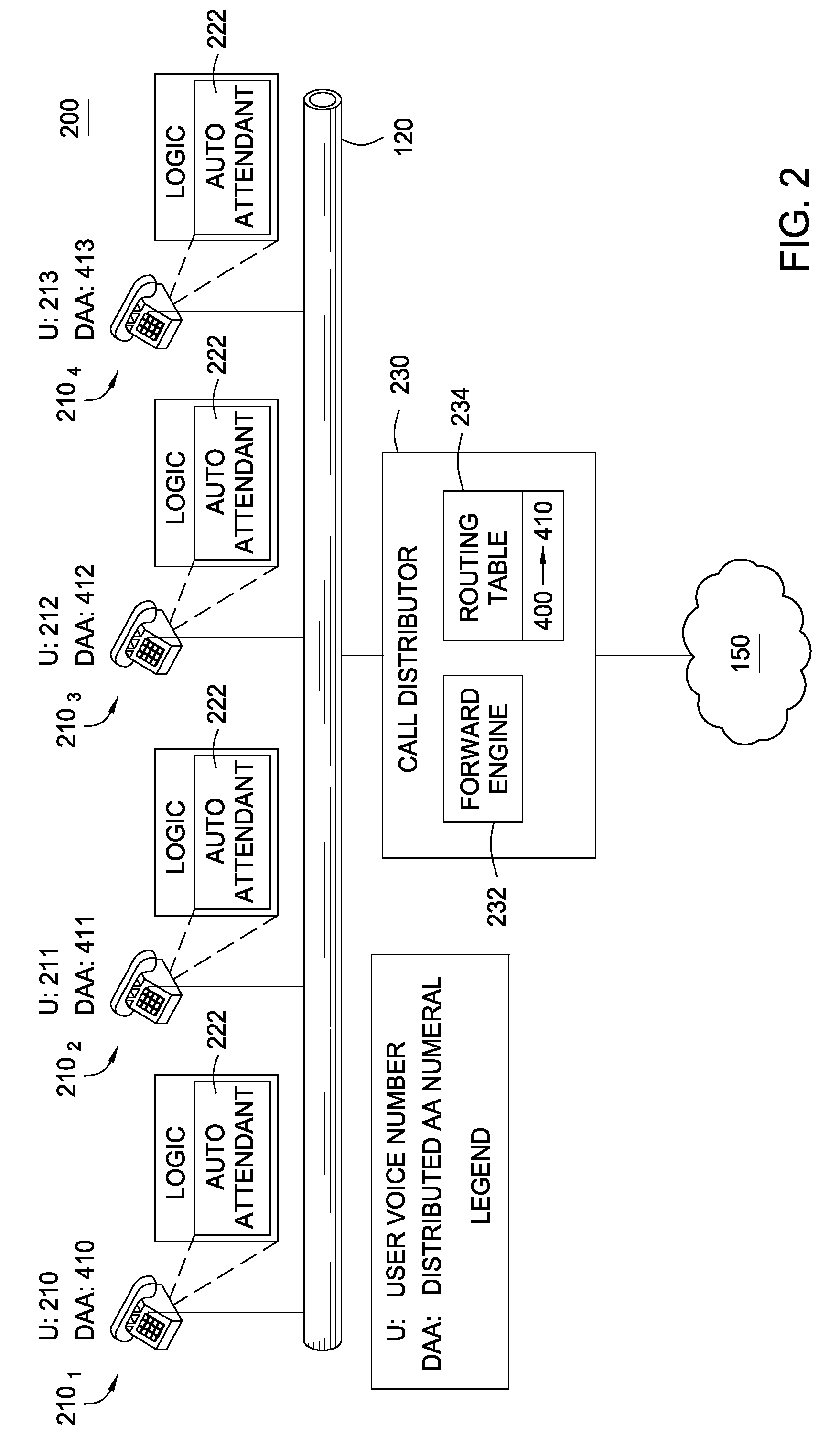
[0018]Embodiments of the present invention generally provide techniques and apparatus that may be used to distribute services in a telephone system. Utilizing these techniques, functions conventionally centralized and run on a separate server may be distributed to end units, for example, as instances of such applications running on network telephones. By distributing these functions, overall system cost and complexity may be reduced by eliminating the need for a separate server. Further, because the functions may be distributed to multiple end units, a level of redundancy may also be achieved. For example, in the event one end unit fails, distributed functions may still be provided by another end unit, resulting in increased network reliability.

[0019]Aspects of the present invention may be embodied in executable software resident in VoIP end units (e.g., as distributed instances of an auto-attendant) and / or network interface devices such as a gateway and / or router (e.g., to distribu...


PUM


Abstract

Embodiments of the present invention generally provide techniques and apparatus that may be used to distribute services in a telephone system. Utilizing these techniques, functions conventionally centralized and requiring a separate server may be distributed to end units, for example, as instances of such applications running on network telephones. Examples of such functions include, but are not limited to, auto attendant functions, distributed voice mail functions, and operator functions.

Description

BACKGROUND OF THE INVENTION[0001]1. Field of the Invention[0002]Embodiments of the present invention generally relate to network-based phone systems. More particularly, embodiments of the present invention relate to distributing functions that are conventionally centralized and require separate hardware servers, such as auto-attendant services, to user endpoints.[0003]2. Description of the Related Art[0004]Voice over Internet Protocol (VoIP) technology has evolved to the point that network telephone systems can provide feature-rich services that rival or surpass those provided by conventional (analog) telephone systems. Examples of such features include call forwarding, voicemail and auto-attendant services (e.g., where a voice leads a caller through a set of menus via voice or touch-tone commands).[0005]FIG. 1 illustrates an example of a network telephone system 100 that provides conventional centralized auto-attendant services. As illustrated, the system 100 includes a series of e...

Claims


Application Information

Patent Timeline
IPC IPC(8): H04M3/42
CPCH04M3/42374H04M3/53325H04M3/51
Inventor PLATZER, DAVID BRUCEWEEREN, ERIC K.
Owner CISCO TECH INC
Why Eureka
Try Eureka