Passive optical network user terminal and method of power supply control and power supply state reporting for the same

a technology of optical network and user terminal, applied in the field of user terminal, can solve problems such as increased power consumption, and achieve the effects of enhancing the user's ability to maintain and manage the user terminal equipment, reducing the power consumed by the equipment, and prolonging the time of the backup power sour

Active Publication Date: 2011-12-06
HUAWEI TECH CO LTD
View PDF39 Cites 55 Cited by
  • Summary
  • Abstract
  • Description
  • Claims
  • Application Information

AI Technical Summary

Benefits of technology

First, by setting a PSCU in the PON user terminal, the embodiment of the present disclosure allows activation of the energy-saving power supply to the SPUs, SDDU, or PONIU within the PON user terminal through the PSCU in the event that the PON user does not use a service in the user terminal equipment. The present disclosure also allows activation of the energy-saving power supply to the SPUs, SDDU, or PONIU through the PSCU upon detecting the resumption of the service, thereby significantly reducing the power consumed by the equipment. Secondly, the embodiment of the present disclosure enables the user to extend the time that the backup power source is able to support critical services by giving up some other services, that is, by activating the energy-saving power sup...

Problems solved by technology

Incorporation of various service processing units (SPUs) int...

Method used


Image

  • Passive optical network user terminal and method of power supply control and power supply state reporting for the same
  • Passive optical network user terminal and method of power supply control and power supply state reporting for the same
  • Passive optical network user terminal and method of power supply control and power supply state reporting for the same

Examples


Embodiment Construction

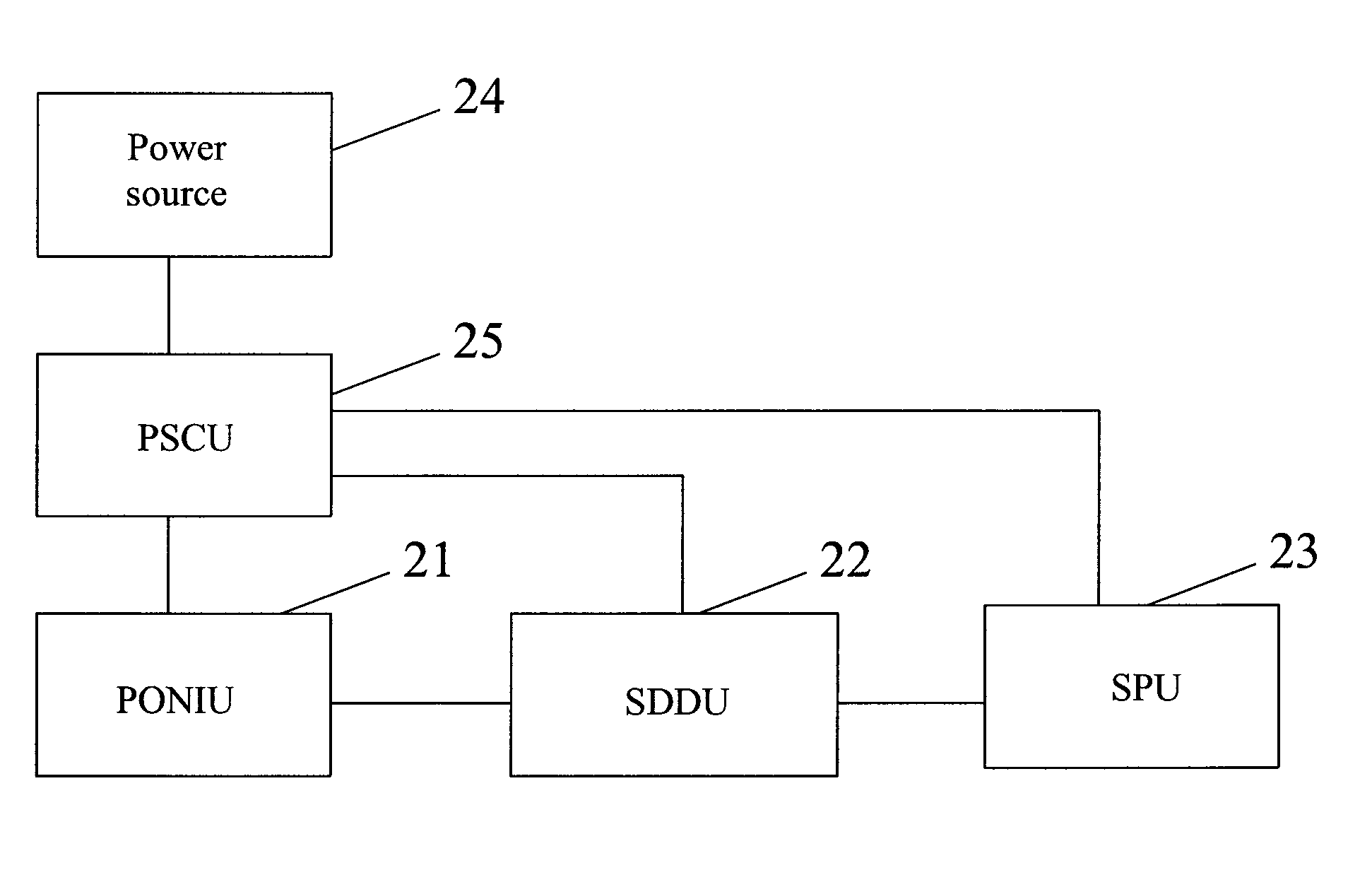
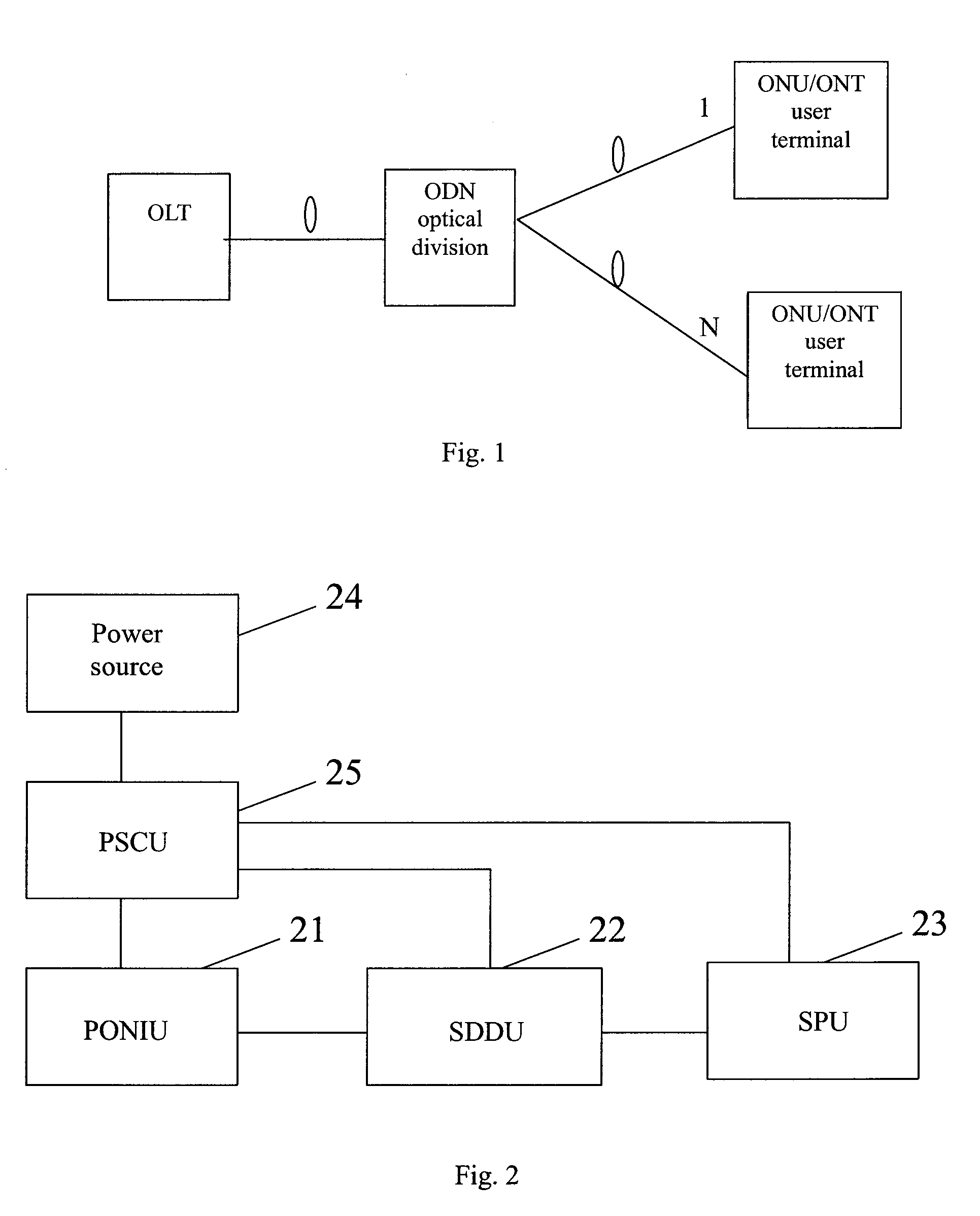
Referring to FIG. 2, a schematic drawing illustrates the main components of a PON user terminal of the embodiment of the present disclosure. As shown in FIG. 2, the PON user terminal of the embodiment of the present disclosure comprises a PONIU 21 for accessing the PON system, a SDDU 22 connected to the PONIU for distributing service data from the PON, and a plurality of SPUs 23 connected to the SDDU 22 for receiving and accordingly processing the service data distributed by the SDDU 22. In an embodiment, the SPUs can be video SPUs, voice SPUs, data access SPUs, wherein each SPU 23 provides a different service via a different type of interface, for example a cable television (CATV) coaxial cable interface, a telephone RJ45 interface, or an Ethernet port. The PON user terminal of the present disclosure further comprises a power source 24 for supplying power to individual units. Further, the PON user terminal of the present disclosure additionally comprises a PSCU 25 for controlling t...


PUM


Abstract

The present disclosure discloses a passive optical network (PON) user terminal comprising a passive optical network interface unit (PONIU) having access to a PON system, a service data distribution unit (SDDU) connected to the PONIU for distributing service data, a plurality of service processing units (SPUs) for receiving and accordingly processing the service data distributed by the SDDU, a power source for providing power to the above units, and a power supply control unit (PSCU) for controlling the activating/deactivating of the energy-saving power supply to the SPUs, the SDDU, and the PONIU. The present disclosure further provides a method for controlling the PON power supply and for reporting the power supply state. The present disclosure allows control of the energy usage of the PON user terminal to save power when a service in the PON user terminal is not used or when the user terminal uses a backup power source to supply power.

Description

CROSS-REFERENCE TO RELATED APPLICATIONSThis application is claiming priority of Chinese Application No. 200610082274.5, filed May 17, 2006, and Chinese Application No. 200510120786.1, filed Dec. 20, 2005, both of which are entitled “Passive Optical Network User Terminal and Method of Power Supply Control and Power Supply State Reporting for the Same” and are incorporated by reference herein in their entirety.BACKGROUNDThe present disclosure relates to the passive optical network (PON) technology, and more particularly to a PON user terminal, and a method of power supply control and power supply state reporting for the user terminal.PON technology is an optical access technology developed to support point-to-multipoint applications. Referring to FIG. 1, a PON typically comprises an optical line terminal (OLT) residing in the central office, a plurality of user terminal equipment residing in the user premises, which are typically optical network units (ONUs) or optical network termina...

Claims


Application Information

Patent Timeline
IPC IPC(8): H04J14/00H04L12/56
CPCH04Q11/0067H04J14/0221H04Q2011/0079H04Q2011/0049
Inventor GAO, HAIDONG, YINGHUA
Owner HUAWEI TECH CO LTD
Why Eureka
Try Eureka