Toner conveyer device, process cartridge, and image forming apparatus

a conveyer device and process cartridge technology, applied in the direction of optics, instruments, electrographic processes, etc., can solve the problems of complex control process or reuse process, deterioration in quality, and complex structure of full-color image forming apparatus

Active Publication Date: 2008-04-24
RICOH KK
View PDF26 Cites 51 Cited by
  • Summary
  • Abstract
  • Description
  • Claims
  • Application Information

AI Technical Summary

Benefits of technology

[0013]It is an object of the present invention to at lea...

Problems solved by technology

Therefore, the user needs to periodically exchange parts that deteriorate in quality earlier than the life of the apparatus or a waste-toner container.
Moreover, because the image forming apparatus is installed adjacent to a user of a personal computer in the times of widespread use of personal computers reduction of noise during operation of the image forming apparatus is another problem that needs attention.
Removal of the fiber makes control process or reuse process complicated.
If a full-color image forming apparatus that uses three or ...

Method used


Image

  • Toner conveyer device, process cartridge, and image forming apparatus
  • Toner conveyer device, process cartridge, and image forming apparatus
  • Toner conveyer device, process cartridge, and image forming apparatus

Examples


Embodiment Construction

[0027]Exemplary embodiments of the present invention will be explained below with reference to the accompanying drawings.

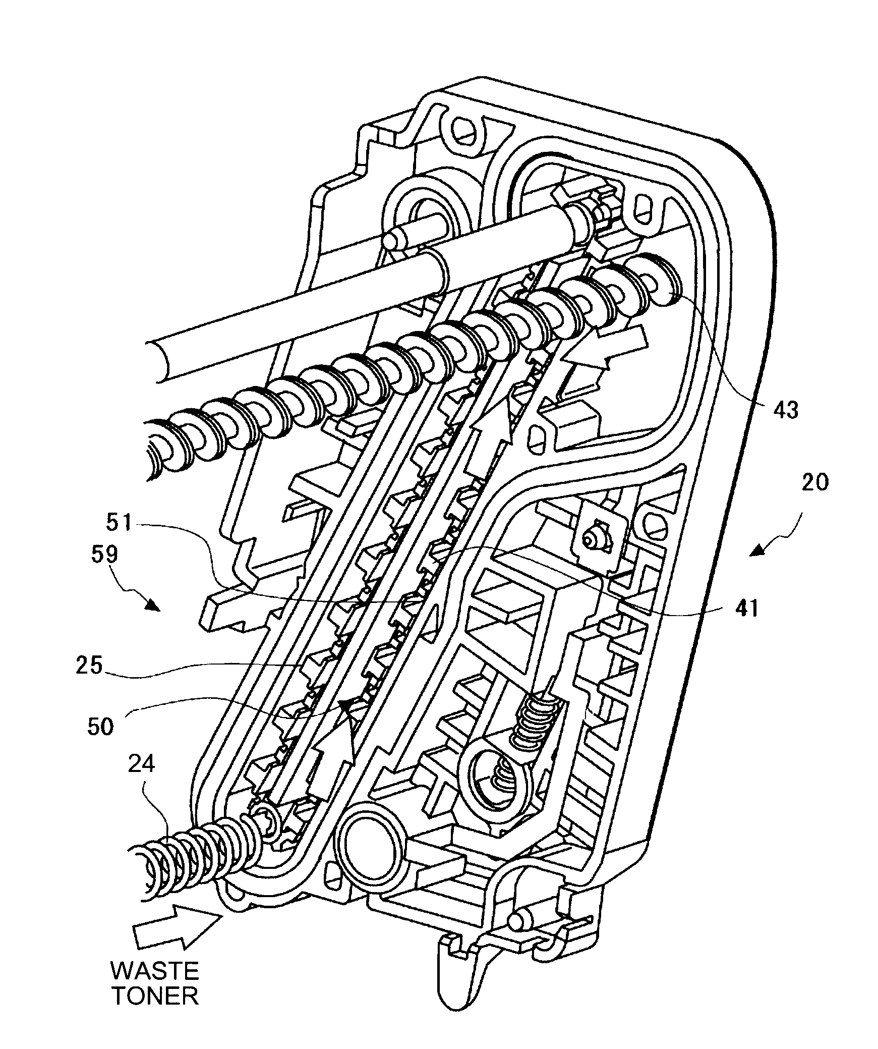
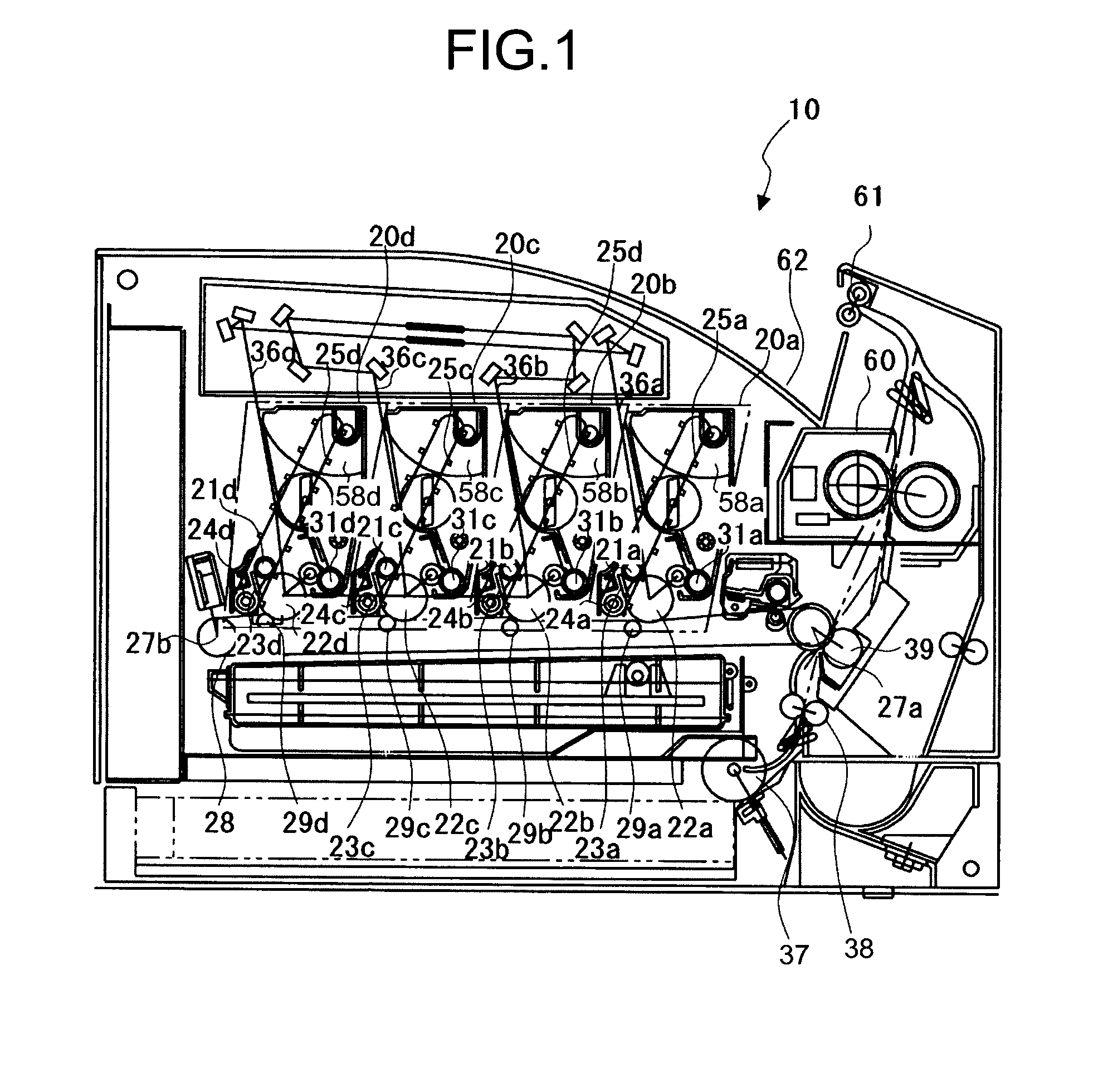
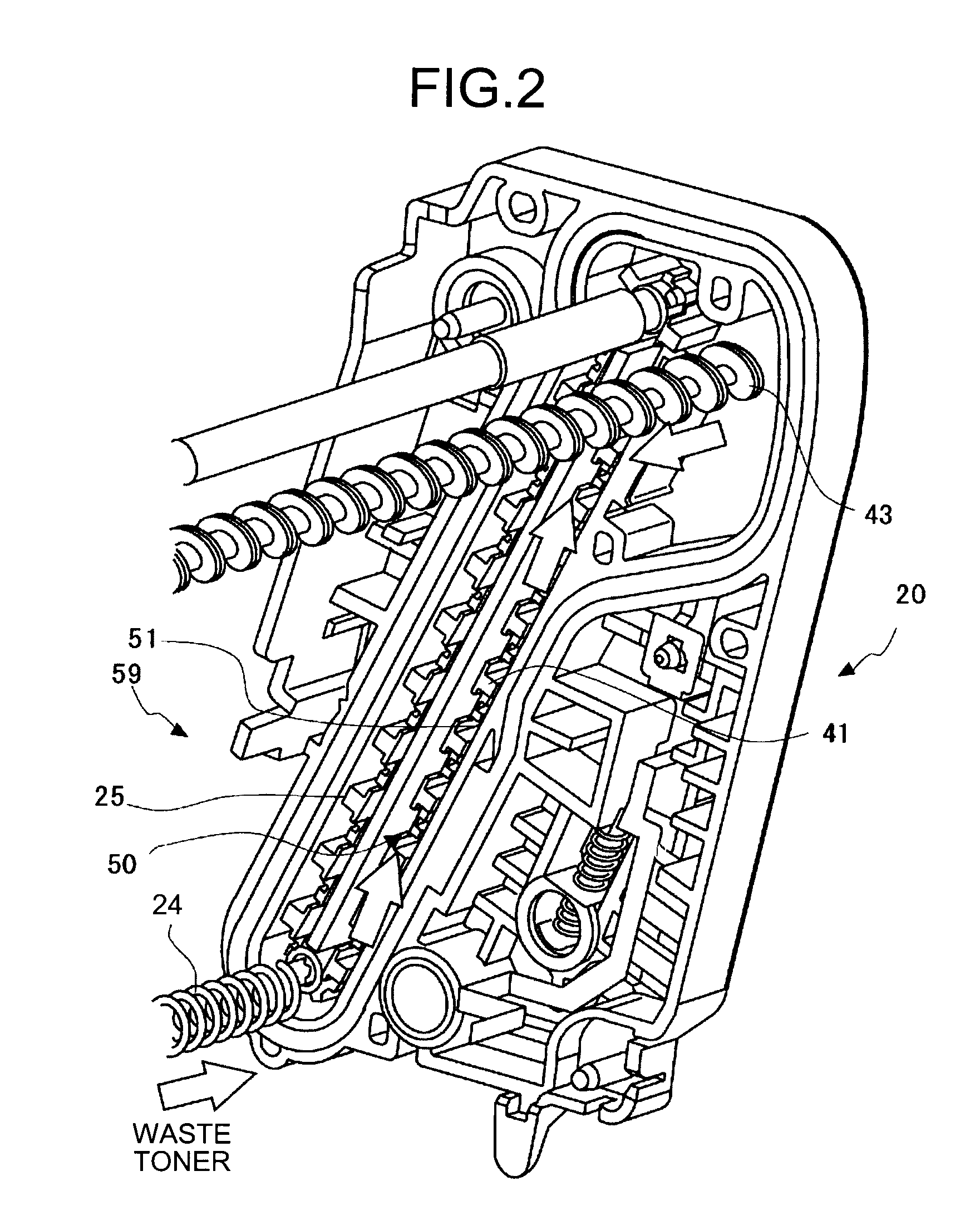
[0028]FIG. 1 is a side view of a color-image forming apparatus 10 including four image forming units 20a, 20b, 20c, and 20d each of which including a photoconductor 22 and a developing device 31 that is arranged on a periphery of the photoconductor 22 in a state that the four image forming units is attached to the image forming apparatus.

[0029]Relevant parts of the color-image forming apparatus 10 are explained with reference to FIG. 1. The four developing devices 31 (31a, 31b, 31c, and 31d) accommodate toners of mutually different colors as developing agents. The photoconductors 22 (22a, 22b, 22c, and 22d) cooperate with a corresponding one of four developing devices 31. Cleaning blades 23 (23a, 23b, 23c, and 23d) that scrape out residual toners after a primary transfer, and charging rollers 21 (21a, 21b, 21c, and 21d) that are brought into contact with the photo...


PUM


Abstract

A toner conveyer device for use in an image forming apparatus includes a toner conveyer belt that conveys waste toner, a screw member that receives the waste toner from the toner conveyer belt and conveys the waste toner to a housing unit, and a scraping member that scraps waste toner that adheres to the screw member.

Description

CROSS-REFERENCE TO RELATED APPLICATIONS[0001]The present application claims priority to and incorporates by reference the entire contents of Japanese priority documents 2006-283258 filed in Japan on Oct. 18, 2006 and 2007-220649 filed in Japan on Aug. 28, 2007.BACKGROUND OF THE INVENTION[0002]1. Field of the Invention[0003]The present invention relates to a toner conveyer device that conveys waste toner.[0004]2. Description of the Related Art[0005]In conventional image forming apparatuses such as copiers, facsimile machines, and printers, a service staff generally carries out replacement of consumable or life-limited components and maintenance of them. However, the trend is changing and the user is carrying out exchange of supplies and maintenance. In addition, smaller components are used for suppressing the size and the cost of the image forming apparatus. Therefore, the user needs to periodically exchange parts that deteriorate in quality earlier than the life of the apparatus or ...

Claims


Application Information

Patent Timeline
IPC IPC(8): G03G21/00
CPCG03G21/105G03G2221/0089
Inventor SHIMIZU, YOSHIYUKIYOSHIDA, TOMOFUMIOOYOSHI, HIROBUMIKATO, KOJITATSUMI, KENZOKAWAKAMI, YOSHIHIROKUBOTA, TOMOHIRO
Owner RICOH KK
Why Eureka
Try Eureka