High pressure lubricant pump for steelworks

Active Publication Date: 2008-04-24
DROPSA
View PDF8 Cites 8 Cited by
  • Summary
  • Abstract
  • Description
  • Claims
  • Application Information

AI Technical Summary

Benefits of technology

[0020]Another object of the invention is to provide a structurally simple pump.
[0021]A further object of the inven

Problems solved by technology

Because of the high stresses in play (caused by the very high pressures) the pump mechanical components can undergo breakage and have to be repaired or replaced.
For example, those components subject to breakage are the piston, the springs and gaskets, the actual cylinder itself being subject to very intense wear.
However, the described traditional pump structure is very complex, resulting in considerable times for dismantling and reassembling the pump for ordinary or extraordinary maintenance.
For example, replacing just one of the aforesaid damaged components means that the pump has to be dismantled, involving an intervention time (making it impossible to use the pump and possibly its entire associated plant) of at least 3-4 hours.
The heating operation is extremely important, particularly when the lubricant is grease because low

Method used


Image

  • High pressure lubricant pump for steelworks
  • High pressure lubricant pump for steelworks
  • High pressure lubricant pump for steelworks

Examples


Example

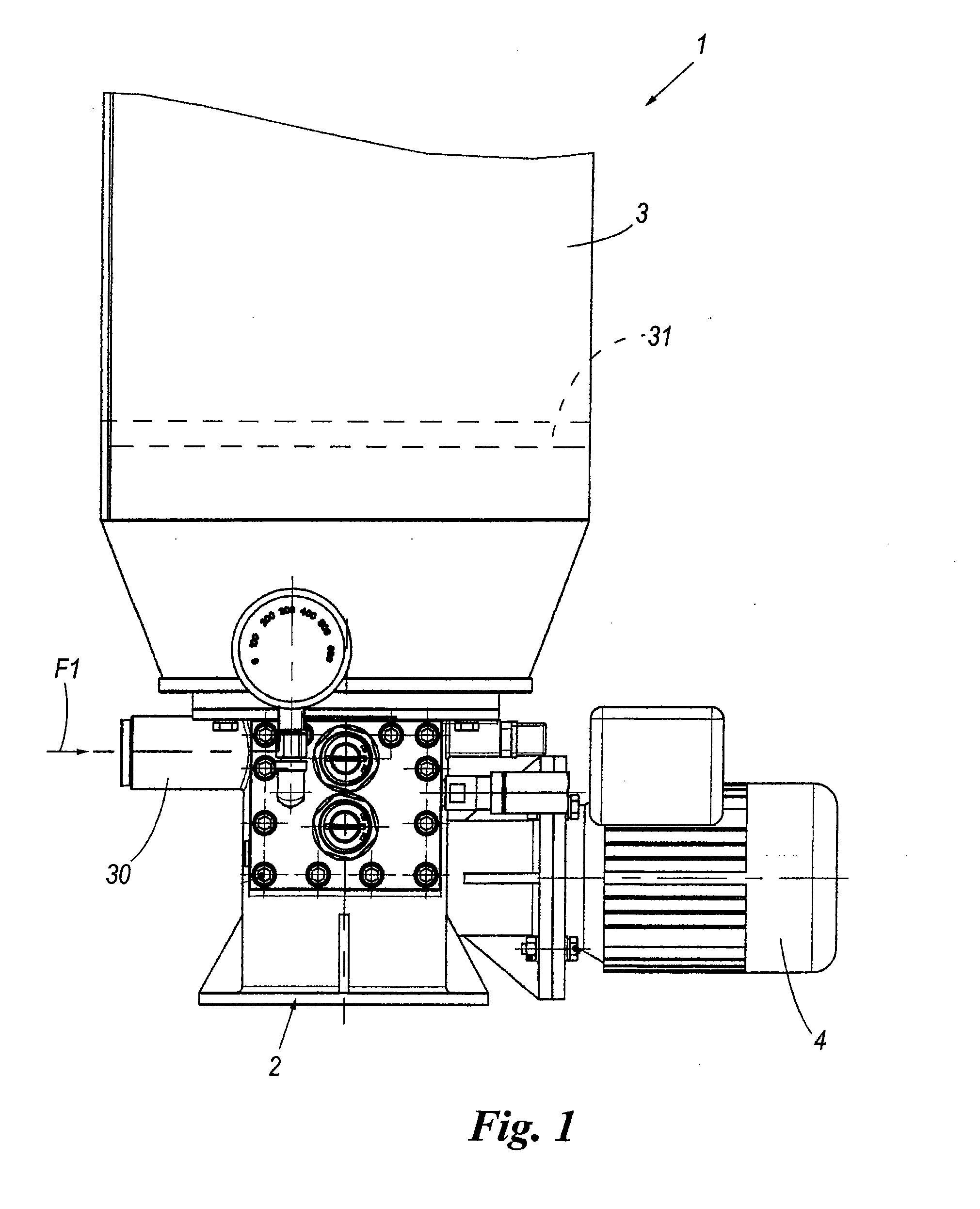
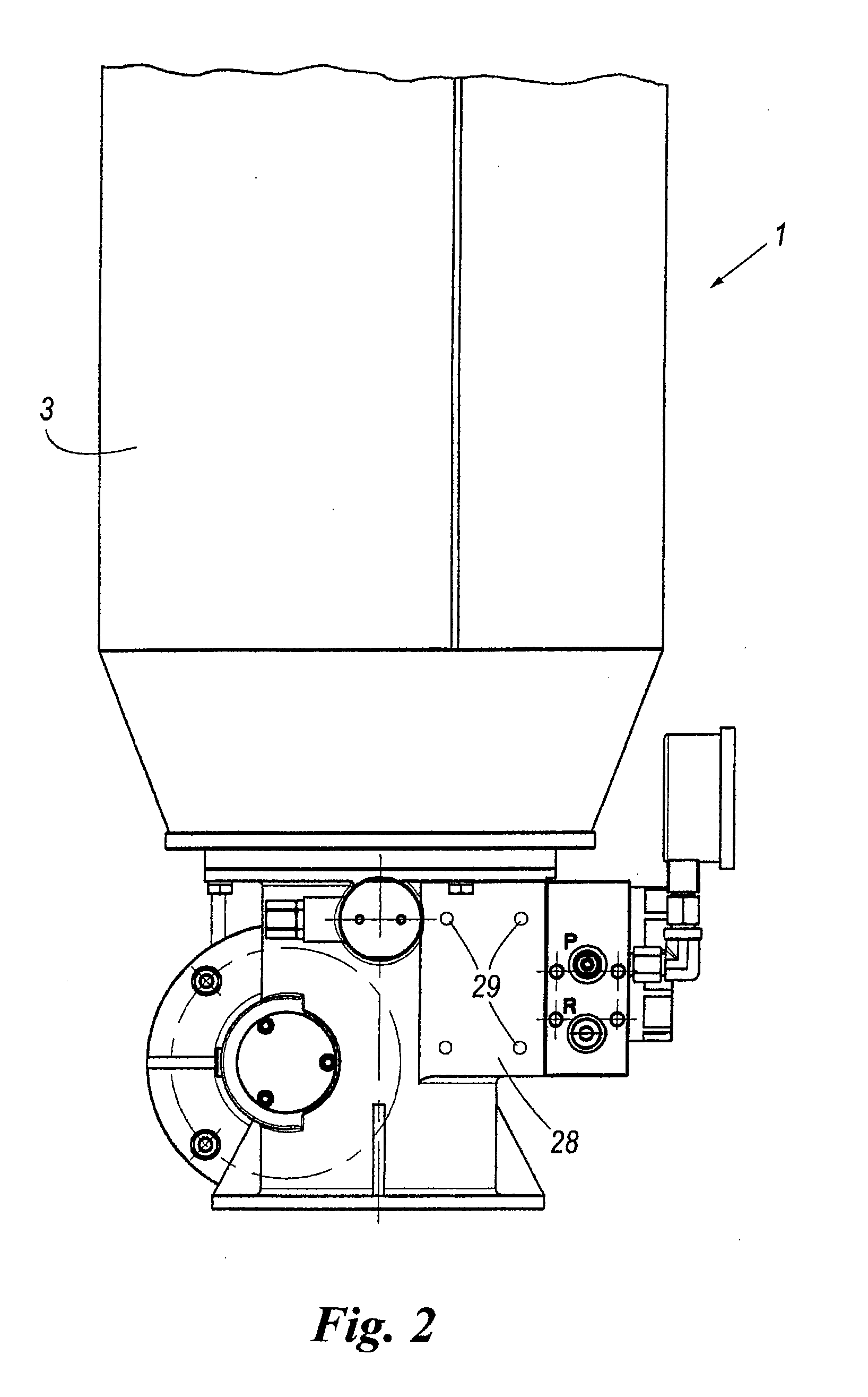
[0032]With reference to said figures, these show a high pressure lubricant pump for steelworks indicated overall by the reference numeral 1.

[0033]The pump 1 comprises generically a body 2 connected to a cylindrical vessel 3 and provided with a drive motor 4.

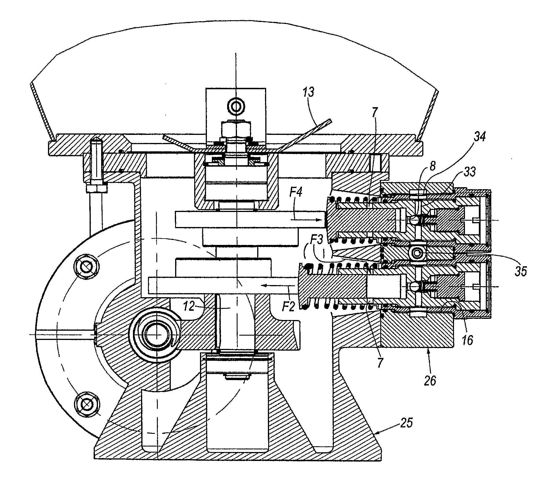
[0034]The body 2 is provided with two cylinders 5 for lubricant pumping, however in other embodiments the number of cylinders can be different, with the body presenting a single cylinder or more than two cylinders.

[0035]Each of the cylinders 5 is provided with lubricant intake ports 7 and a lubricant delivery port 8, for entry of the lubricant to be pumped and for exit of the pressurized lubricant.

[0036]In addition, a piston 10 is movable with reciprocating translatory movement (to-and-fro movement) within each cylinder 5 to pressurize the lubricant.

[0037]Each piston 10 has an end, external to the cylinder 5, associated with a cam 11; as shown in particular in FIG. 3, all the cams 11 are carried by a drive shaft 12 driven in rota...


PUM


Abstract

The high pressure lubricant pump for steelworks comprises a body provided with at least one cylinder provided with a lubricant intake port and a lubricant delivery port. Within the cylinder a piston is movable to pressurize the lubricant. The cylinder and the piston define a pre-assembled pumping unit removably fixed into a seat of the body.

Description

FIELD OF THE INVENTION[0001]The present invention relates to a high pressure lubricant pump for steelworks.BACKGROUND OF THE INVENTION[0002]In steelworks it is known to use pumps for feeding lubricant (in the form of oil or grease) at a high pressure which can reach very high values, up to 450 / 500 atmospheres.DISCUSSION OF THE RELATED ART[0003]These pumps are usually in the form of a body defining one or usually more cylinders within which pistons are movable, each against a spring.[0004]The pistons are operated by cranks or cams (because of the high pressures and hence stresses in play).[0005]Because of the high stresses in play (caused by the very high pressures) the pump mechanical components can undergo breakage and have to be repaired or replaced.[0006]For example, those components subject to breakage are the piston, the springs and gaskets, the actual cylinder itself being subject to very intense wear.[0007]However, the described traditional pump structure is very complex, res...

Claims


Application Information

Patent Timeline
IPC IPC(8): F04B1/02
CPCF04B53/162F16N13/02F04B53/22Y10T137/7927
Inventor DIVISI, WALTER
Owner DROPSA
Why Eureka
Try Eureka