Container and analysis container using the same

Inactive Publication Date: 2010-10-07
ARKRAY INC
View PDF6 Cites 0 Cited by
  • Summary
  • Abstract
  • Description
  • Claims
  • Application Information

AI Technical Summary

Benefits of technology

[0005]Hence, the present invention is intended to provide a vessel easily capable of being open

Problems solved by technology

Therefore, with respect to the autoanalyzer, the number of apparatus mechanisms is increased

Method used


Image

  • Container and analysis container using the same
  • Container and analysis container using the same
  • Container and analysis container using the same

Examples


Example

Example 1

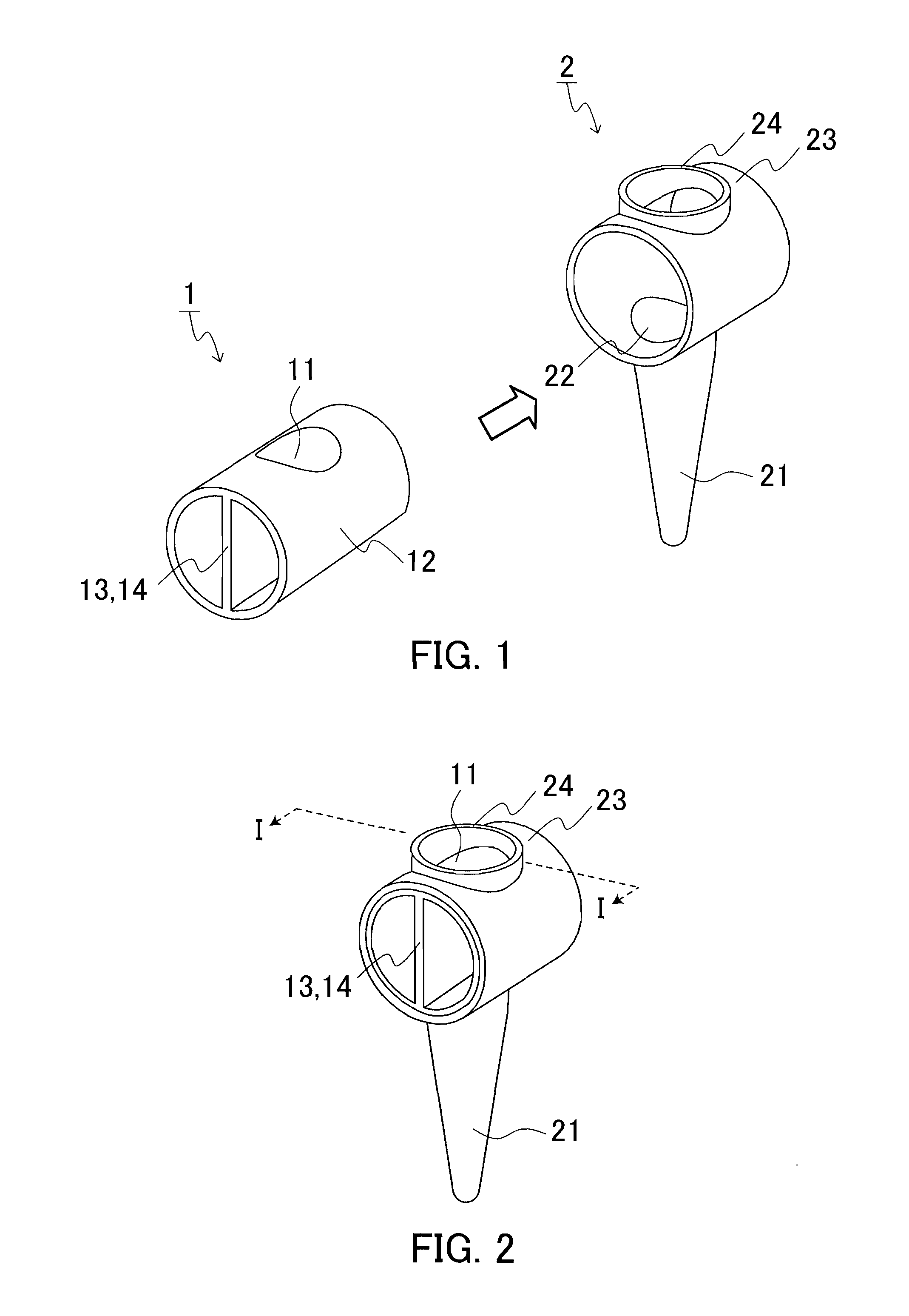
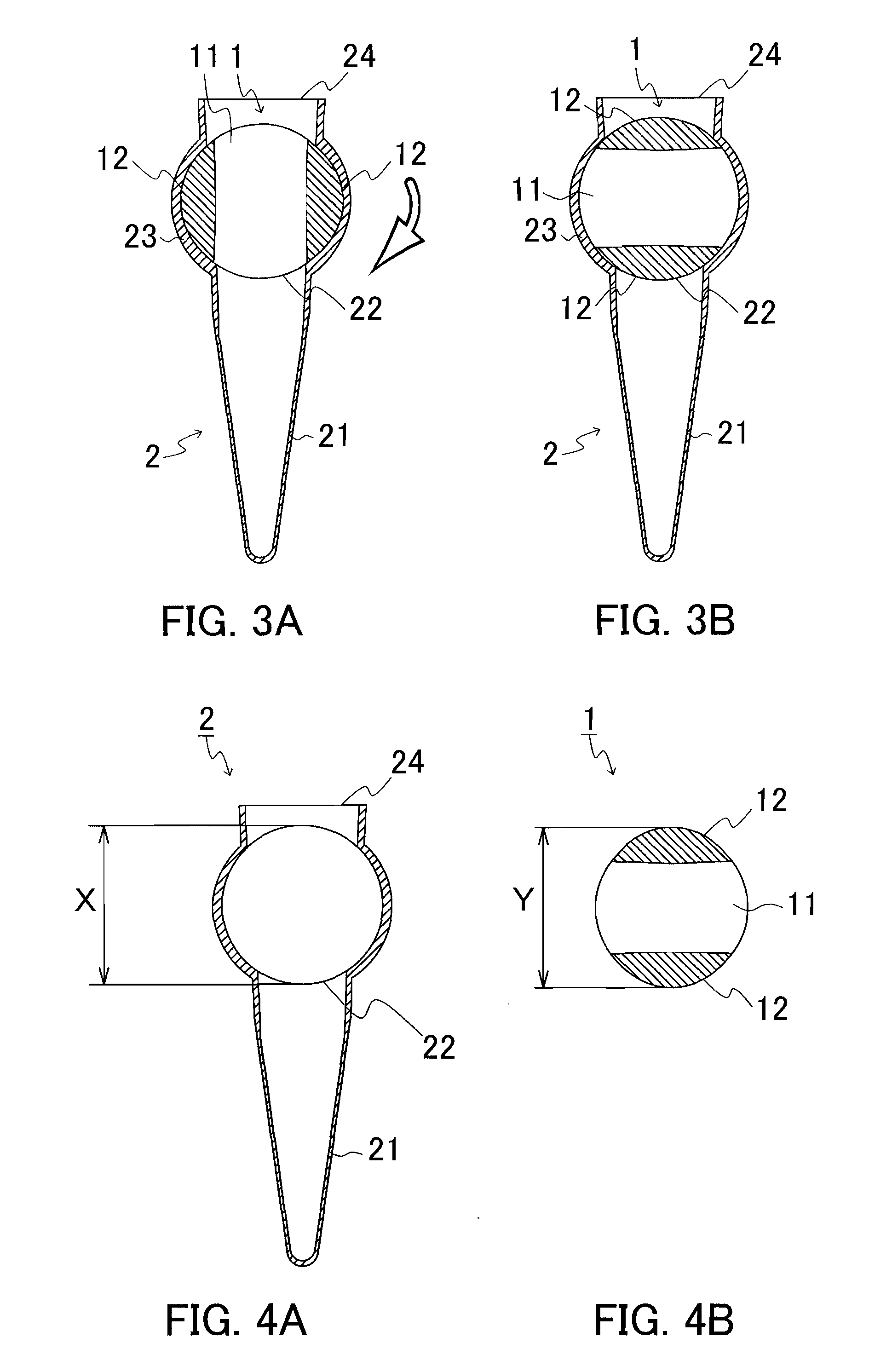
[0038]An example of a vessel of the present invention is shown in FIGS. 1 to 4. FIG. 1 is an exploded perspective view of a vessel of Example 1. FIG. 2 is a perspective view of the vessel of Example 1. FIG. 3 is a cross-sectional view of the vessel of Example 1 taken along line I-I of FIG. 2. FIG. 4 (A) is a cross-sectional view of a vessel body and FIG. 4 (B) is a cross-sectional view of a cover body. In FIGS. 1 to 4, identical parts are indicated with identical numerals and symbols.

[0039]As shown in FIGS. 1 to 4, a cover body 1 is cylindrical columnar and has a through-hole 11 in a direction perpendicular to an axial direction of the cylindrical column and two sealing positions 12 placed at positions shifted from an opening of the through-hole 11 in a peripheral direction. The two sealing positions 12 are opposed to each other in a radial direction of the cover body 1. The through-hole 11 is formed so as to be placed at a position corresponding to a side wall opening port...

Example

Example 2

[0048]Another example of a vessel of the present invention is shown in FIGS. 6 and 7. FIG. 6 is an exploded perspective view of the vessel of Example 2. FIG. 7 is a perspective view of the vessel of Example 2. In FIGS. 6 and 7, identical parts to those shown in FIGS. 1 to 5 are indicated with identical numerals and symbol's.

[0049]As shown in FIGS. 6 and 7, in the vessel of Example 2, plural plate-like holding portions 27 are formed in a vertical direction at an outer peripheral surface of the cover body containing portion 23 adjacent to the side wall opening portion 24. Other than these, the structure and the usage pattern of the vessel of Example 2 are similar to those of the vessel of Example 1. Since the vessel of Example 2 includes the holding portions 27, it easily can be held by an analyzer or a human hand, and thereby the vessel easily can be attached to or detached from the analyzer. In the vessel of Example 2, in the same manner as in Example 1, the number of the s...

Example

Example 3

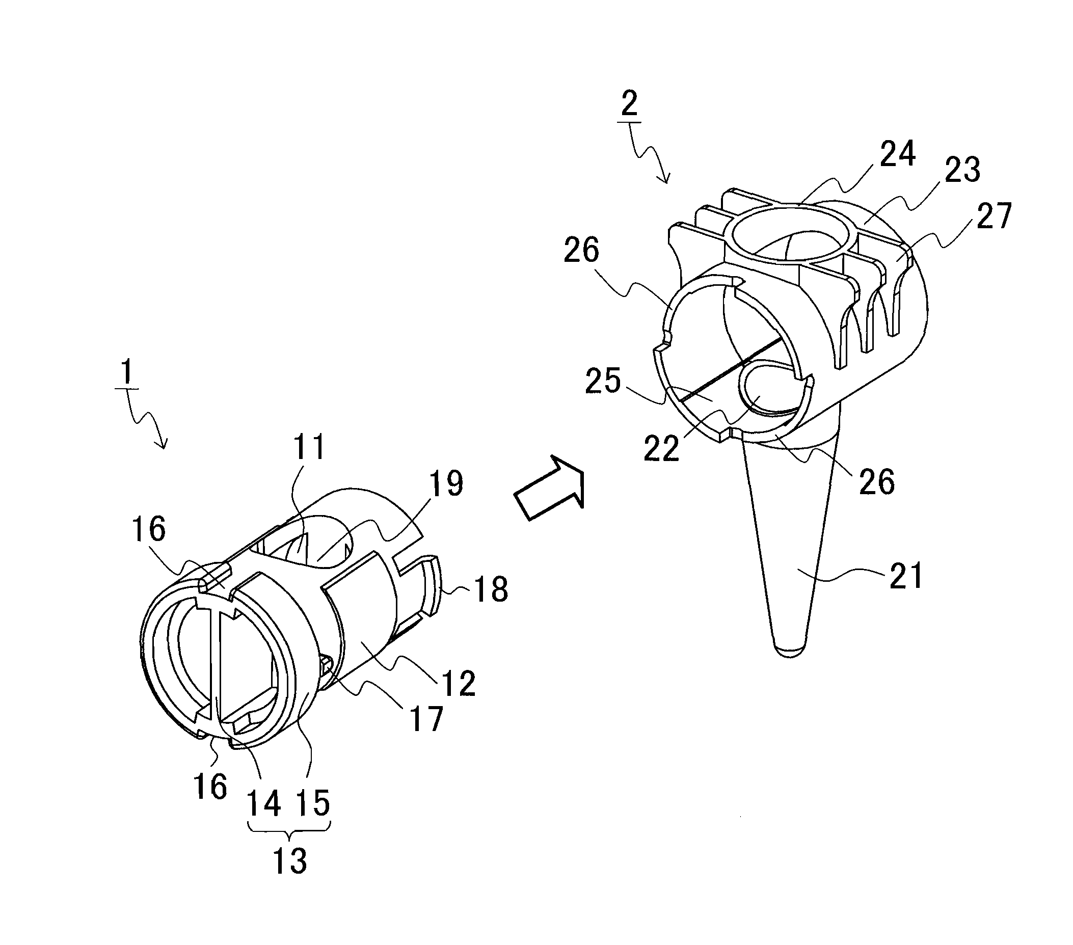
[0051]Another example of a vessel of the present invention is shown in FIGS. 8 and 9. FIG. 8 is an exploded perspective view of the vessel of Example 3. FIG. 9 is a perspective view of the vessel of Example 3. In FIGS. 8 and 9, identical parts to those shown in FIGS. 1 to 7 are indicated with identical numerals and symbols.

[0052]As shown in FIGS. 8 and 9, in the vessel of Example 3, a rotation operating ring 15, an opening and closing recognizing portion 16 (an apparatus switch), a stopping portion 17, a latching portion 18, and a support plate 19 further are arranged on the cover body 1. The sealing position 12 is formed as a thin plate, and a ribbed surface 25 and a rotation adjusting portion 26 are further arranged on the vessel body 2. Other than these, the structure of the vessel of Example 3 is similar to that of the vessel of Examples 1 and 2. Further, the usage pattern of the vessel of Example 3 is similar to that of the vessel of Examples 1 and 2 except for the usa...


PUM


Abstract

A vessel, which can easily be opened and closed without detaching and attaching a cover, is provided. The vessel of the present invention includes a vessel body 2 and a cover body 1. In a condition where the cover body 1 is contained in a cover body containing portion 23, the cover body 1 is rotated and an inside of a vessel main body 21 is communicated with a side wall opening portion 24 formed on a side wall of the cover body containing portion 23 through the through-hole 11. When the cover body 1 is rotated and the sealing position 12 is placed above an upper open-end 22 of the vessel main body 21, an inside of the vessel main body 21 can be sealed from the outside.

Description

TECHNICAL FIELD[0001]The present invention relates to a vessel and an analysis vessel using the same.BACKGROUND ART[0002]Conventionally, in an analysis using a physical and chemical analysis apparatus, a medical analysis apparatus, and the like, a vessel that stores an object to be analyzed has been used. In order to prevent deterioration in the analysis accuracy due to evaporation and dispersion of a sample in a vessel during an analysis, the vessel is required to be sealed in an air-tight and liquid-tight manner. Therefore, in conventionally used vessels, for example, a screw cap structure and a fit-in structure (for example, Patent Document 1) are used. The screw cap structure is provided with a packing and the fit-in structure uses flexibility of resin. Accordingly, conventional vessels require operations of removing a cover, moving the thus removed cover elsewhere, reattaching the removed cover, and the like at the time of opening and closing the vessels.[0003]In contrast, in a...

Claims


Application Information

Patent Timeline
IPC IPC(8): C12M1/24B01L3/00
CPCB01L3/50825B01L2300/049F16K5/0492F16K3/262G01N2035/0405B01L2400/0644A61J1/00G01N35/00
Inventor FURUSATO, NORIAKI
Owner ARKRAY INC
Why Eureka
Try Eureka