Golf ball with colored impact zone

a golf ball and impact zone technology, applied in the field of golf balls, can solve the problems of limited use of innovations, poor inability to produce enough, so as to improve the visual acuity of golfers, easy identification

Inactive Publication Date: 2008-04-24
KANG JOHN J
View PDF13 Cites 13 Cited by
  • Summary
  • Abstract
  • Description
  • Claims
  • Application Information

AI Technical Summary

Benefits of technology

[0008]According to one aspect of the present invention, a golf ball has a bright colored shape, termed as the impact zone, on two opposite sides of the golf ball. The shape creates a bright color contrast with the typical white background of the ball. Differing colors can be used so long as they are brightly colored. Hues of orange and red will typically produce the best contrast on the white background of the ball and the green of the grass. It is this color contrast that helps with the golfer's visual acuity. The shape does not have to be the same on each side, but can be. In one embodiment, the shape is an octagonal shape on one side and a circular shape on the other. Other shapes may include circular, square, triangle, or any multi-sided shape. The shapes may vary in size, but should be sufficiently large for easy identification by the golfer for best visualization. Having different size shapes for the impact zones enables golfers of any skill level to use the ball. For example, less skilled golfers or golfers with poor eyesight may choose to use the larger impact zone, while more highly skilled golfers or golfers with good eyesight may choose to use the smaller sized impact zone.

Problems solved by technology

However, these innovations do little for golfers with worsening or developing eye-hand coordination, such as elderly or youth golfers, respectively.
Mis-hits, “shanks”, “topping”, and hitting the ball “fat” are all common errors due to improper ball striking.
This, obviously, is not the case, due to factors such as poor vision, poor lighting (e.g., dusk or dawn), or poor playing conditions (e.g., cloudy, rainy, or windy).
Thus, these innovations have limited use, since they only aid in putting and not necessarily tee shots, chip shots, bunker shots, etc.
However, repeating symmetrical patterns may not produce enough contrast with the golf ball's white background to enhance visual perception since a repeating pattern will mute out the white of the ball, thereby reducing the ability of the golfer to focus.
Also, simply repeating symmetrical patterns cannot aid the directional alignment of the golfer to the golf ball, which is also critical for ball striking.

Method used


Image

  • Golf ball with colored impact zone
  • Golf ball with colored impact zone

Examples


Embodiment Construction

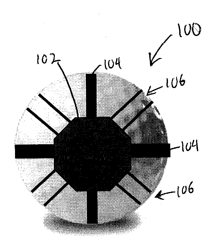
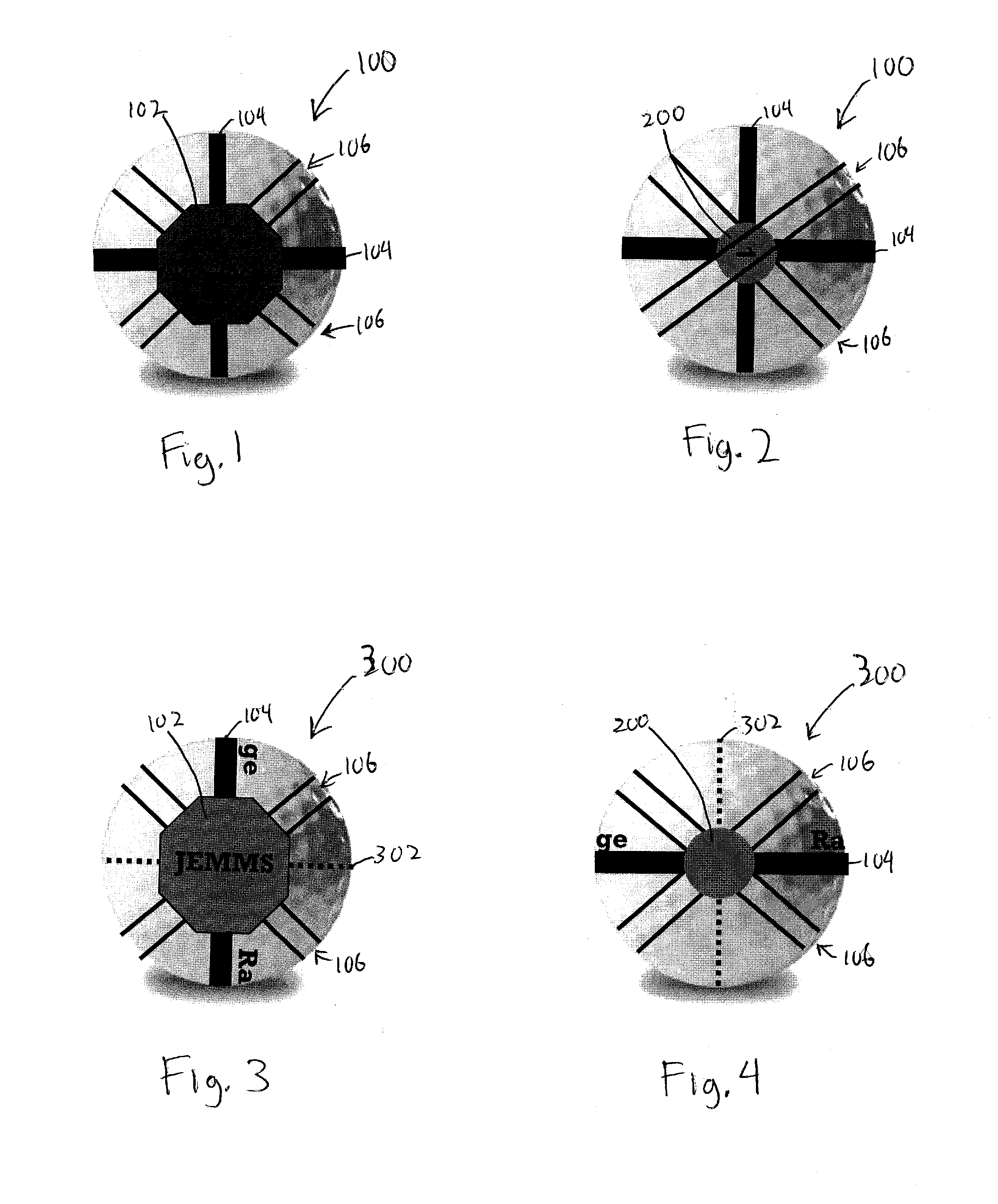
[0016]According to one aspect of the present invention, a golf ball has two impact zones, both of differing sizes and shapes to match the golfer's experience level and eye-hand coordination. Experienced golfers may only need the smaller target, whereas beginners or older golfers may want the larger impact zone. In both cases, the impact zones aid the golfer to see the golf ball by way of the color contrast between the impact zone and the golf ball background. The zone color can be any bright color so long as there is a clear contrast to the golf ball background, which is typically white, but not necessarily limited to just white. According to another embodiment, colored sight lines emanate from the impact zones to aid the golfer with alignment and / or stance.

[0017]FIGS. 1 and 2 show one embodiment of a golf ball 100 according to one embodiment. FIG. 1 shows one side of golf ball 100 with a larger impact zone 102. As shown, impact zone 102 is an octagonal shape, but other shapes, such...


PUM


Abstract

A golf ball has colored lines emanating from colored visual impact zones of the ball to form a useful alignment tool as well as directional indicators. The visual impact zones are located on opposite ends of the golf ball. The utility of such a colored design on the golf ball aids the golfer in seeing the ball to improve with eye-hand coordination and proper alignment of the golfer's body to the ball in order to produce a better ball striking result.

Description

BACKGROUND[0001]1. Field of Invention[0002]The present invention relates to golf balls, and in particular, to visual designs on golf balls.[0003]2. Related Art[0004]Innovations in golf ball technology generally stem from improving its flight characteristics, such as distance or trajectory. However, these innovations do little for golfers with worsening or developing eye-hand coordination, such as elderly or youth golfers, respectively. For this segment of golfers, it is more imperative to see the ball and hit it cleanly in the right spot. Mis-hits, “shanks”, “topping”, and hitting the ball “fat” are all common errors due to improper ball striking. A golf ball that helps golfers see the ball more clearly can reduce the errors involved.[0005]One type of golf ball innovation deals with improving sight lines for putting. Some of these types of innovations related to alignment for putting can be found in U.S. Pat. Nos. 676,506, 1,842,944, 2,709,595, 3,420,529, 3,753,565, 4,209,172, 4,235...

Claims


Application Information

Patent Timeline
Patent Type & Authority Applications(United States)
IPC IPC(8): A63B37/00A63B69/36
CPCA63B24/0021A63B37/0003A63B37/0011A63B2024/0031A63B43/008A63B69/3655A63B69/3688A63B37/0022
Inventor KANG, JOHN J.
Owner KANG JOHN J
Why Eureka
Try Eureka