Automatic transmission control apparatus

a transmission control and automatic technology, applied in mechanical devices, instruments, road transportation, etc., can solve the problems of difficult to adopt a control that focuses on the rotational speed difference and the transmission torque distribution of frictional engaging elements, and achieves the effect of easy application and small shock

Inactive Publication Date: 2008-04-24
JATCO LTD
View PDF5 Cites 46 Cited by
  • Summary
  • Abstract
  • Description
  • Claims
  • Application Information

AI Technical Summary

Benefits of technology

[0019]The present invention was conceived in view of the issues described above. In view of the above-mentioned issues, one object is to provide an automatic transmission control apparatus and method that can accomplish frictional engaging element interchange control in a simple manner, particularly...

Problems solved by technology

However, with the technology disclosed in U.S. Pat. No. 5,782,711, it is difficult to ascertain the relationship between the control results of engaging frictional engaging element and the releasing frictional engaging element and, thus, it is difficult to adopt a control that focuses on the rotational speed differences and transmitted torque distributions of the frictional engaging elements.
Consequently, rotational speed difference ...

Method used


Image

  • Automatic transmission control apparatus
  • Automatic transmission control apparatus
  • Automatic transmission control apparatus

Examples


first embodiment

[0064]Referring now to FIGS. 7 to 11, a twin-clutch transmission control apparatus and a twin-clutch transmission control method in accordance with a first embodiment of the present invention will now be described.

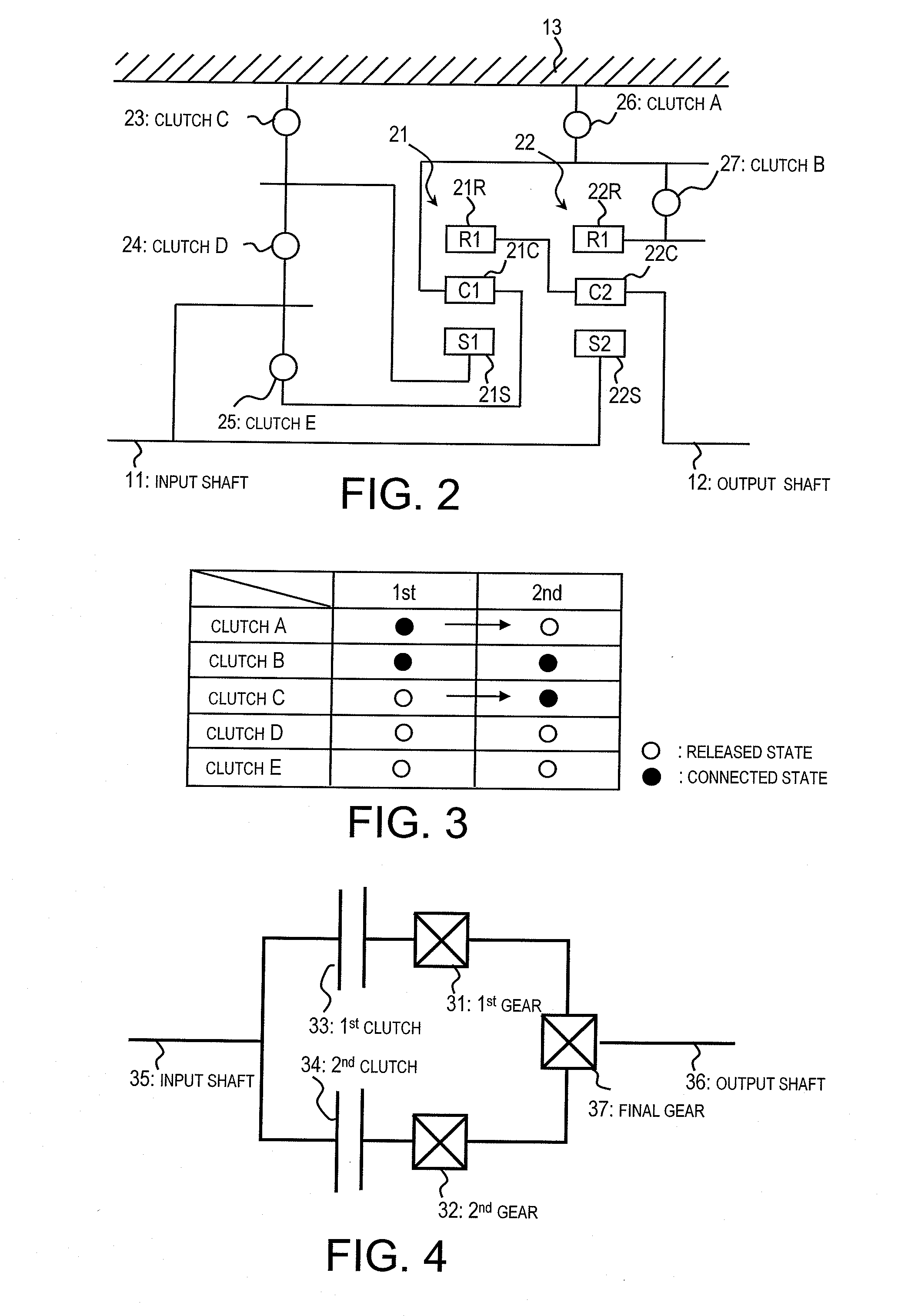
[0065]In this embodiment, an upshift control is employed when one of the first clutch 52 and the second clutch 53 is changed from an engaged state to a released state and the other is changed from a released state to an engaged state in response to a request to change a gear ratio of an automatic transmission of the type described above. The following explanation will treat the first clutch 52 as the first clutch being changed from the engaged state to the released state and the second clutch 53 as the second clutch being changed from the released state to the engaged state. However, the same control can be applied when the first clutch 52 is changed from the released state to the engaged state and the second clutch 53 is changed from the engaged state to the released stat...

second embodiment

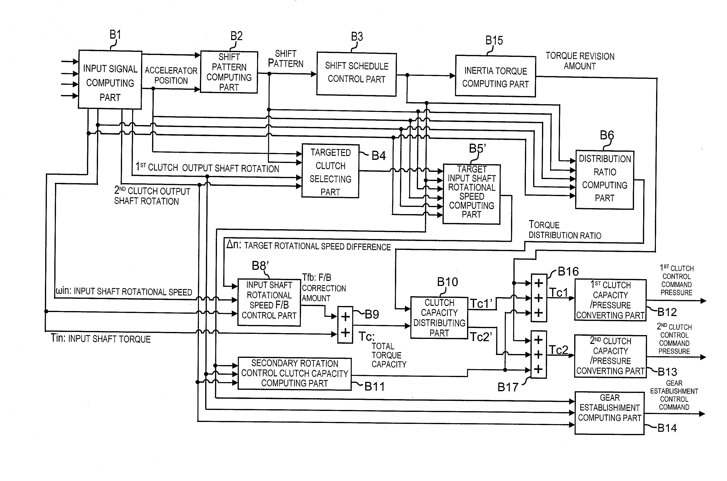
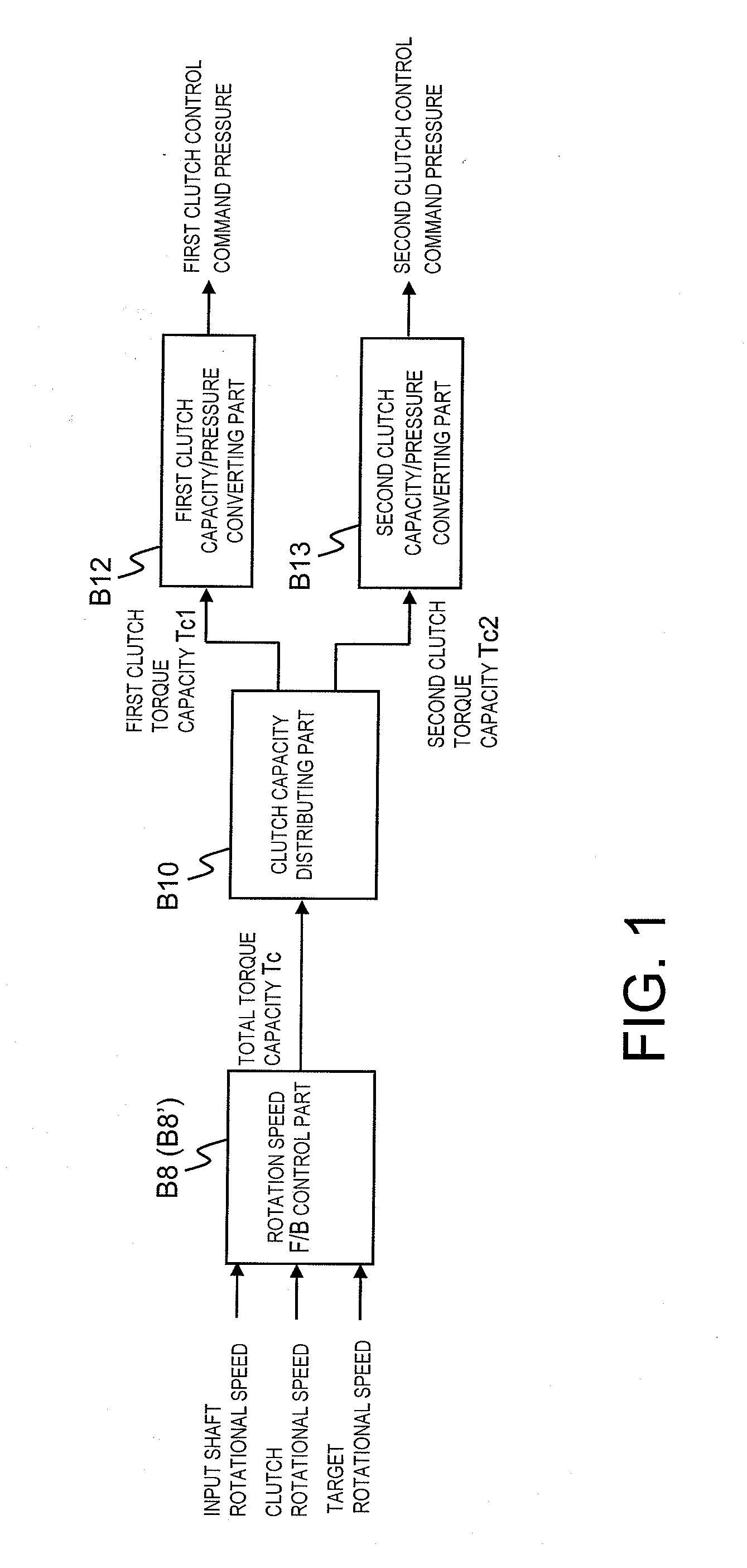
[0152]In this embodiment, a rotational speed difference control of the clutches has been replaced with rotational speed control (rpm control) of the input shaft. In other words, the rotational speed difference control of the previous embodiment controls the difference between the input rotational speed and the output rotational speed of a clutch. However, in this embodiment, the input shaft rotational speed control correlates the input shaft rotational speed of the input shaft to the input rotational speed of the clutch and correlates the vehicle speed and the gear ratio used with the particular clutch to the output rotational speed of the clutch. Rotational speed difference control of the clutches can be replaced with rotational speed control of the input shaft because it can be assumed that the vehicle speed remains substantially unchanged during shifting.

[0153]FIGS. 12 to 15 illustrate a twin-clutch transmission control apparatus and a twin-clutch transmission control method in a...


PUM


Abstract

An automatic transmission control apparatus is provided with a control scheme that focuses on the rotational speed differences of the frictional engaging elements and the distribution of torque transferred by the frictional engaging elements. When the automatic transmission is upshifted while in a power-off state, the individual torque capacity of a frictional engaging element being released and the individual torque capacity of a frictional engaging element being connected are corrected by adding a prescribed torque capacity amount to each of the individual torque capacities during an inertia phase of the shift control in which a compensation is executed for inertia related to changing the gear ratio. In this way, frictional losses are induced in the frictional engaging elements so as to absorb the inertia torque and lower the input rotational speed more quickly.

Description

CROSS-REFERENCE TO RELATED APPLICATIONS[0001]This application claims priority to Japanese Patent Application No. 2006-288783, filed on Oct. 24, 2006. The entire disclosure of Japanese Patent Application No. 2006-288783 is hereby incorporated herein by reference.BACKGROUND OF THE INVENTION[0002]1. Field of the Invention[0003]The present invention generally relates to an automatic transmission control apparatus and method of controlling the automatic transmission. More specifically, the present invention relates to an automatic transmission control apparatus with a plurality of frictional engaging elements that are selectively engaged to achieve a gear, and configured to accomplish upshifting of the automatic transmission when the vehicle is in a power-off running state by interchanging between engagement of a first frictional engaging element serving to achieve a low gear position before shifting and engagement of a second frictional engaging element serving to achieve a high gear po...

Claims


Application Information

Patent Timeline
IPC IPC(8): F16H59/18G06F19/00F16H59/42F16H59/46F16H59/68F16H59/70F16H61/06F16H61/68F16H61/684F16H61/688
CPCF16H59/46F16H61/0437F16H61/061F16H61/686Y10T477/60F16H2061/0462F16H2061/0496Y10T477/692F16H61/688Y02T10/60
Inventor HONMA, TOMOAKIUCHIDA, MASAAKIKATAKURA, SHUSAKUKAWAMOTO, YOSHINOBUFUJIWARA, SADAMU
Owner JATCO LTD
Why Eureka
Try Eureka