Focal plane shutter for digital cameras
a technology for digital cameras and shutters, applied in shutters, instruments, camera diaphragms, etc., can solve the problems of long time required until the first blade starts the exposure operation, high possibility of missing a shutter chance, and difficulty in mass-producing the focal plane shutters constructed in this way, so as to quickly start the exposure operation and quickly recognize errors.
- Summary
- Abstract
- Description
- Claims
- Application Information
AI Technical Summary
Benefits of technology
Problems solved by technology
Method used
Image
Examples
embodiment 1
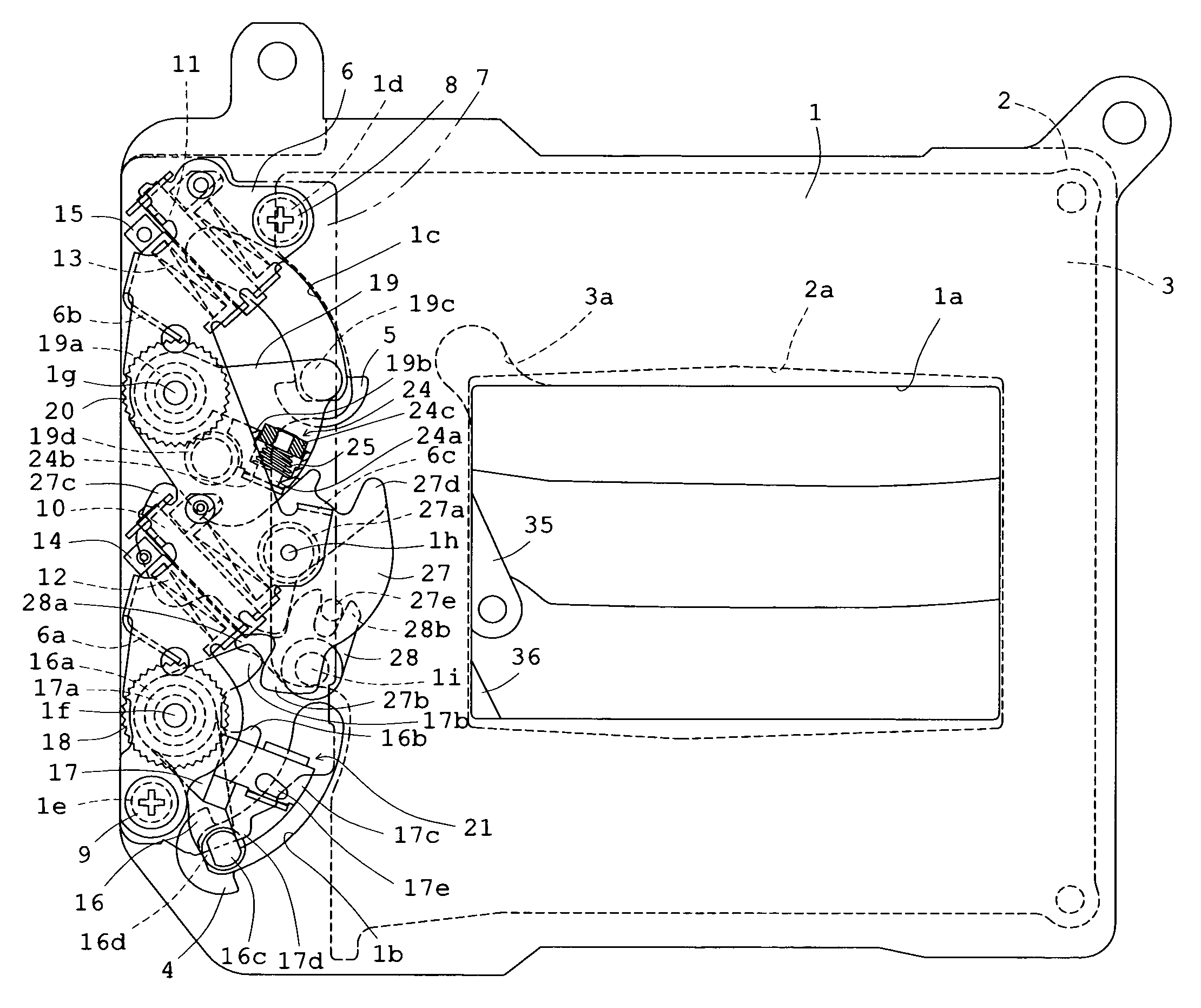
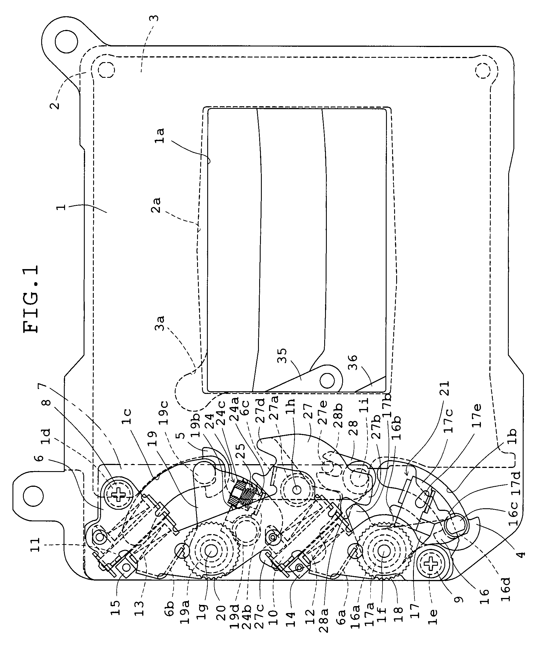
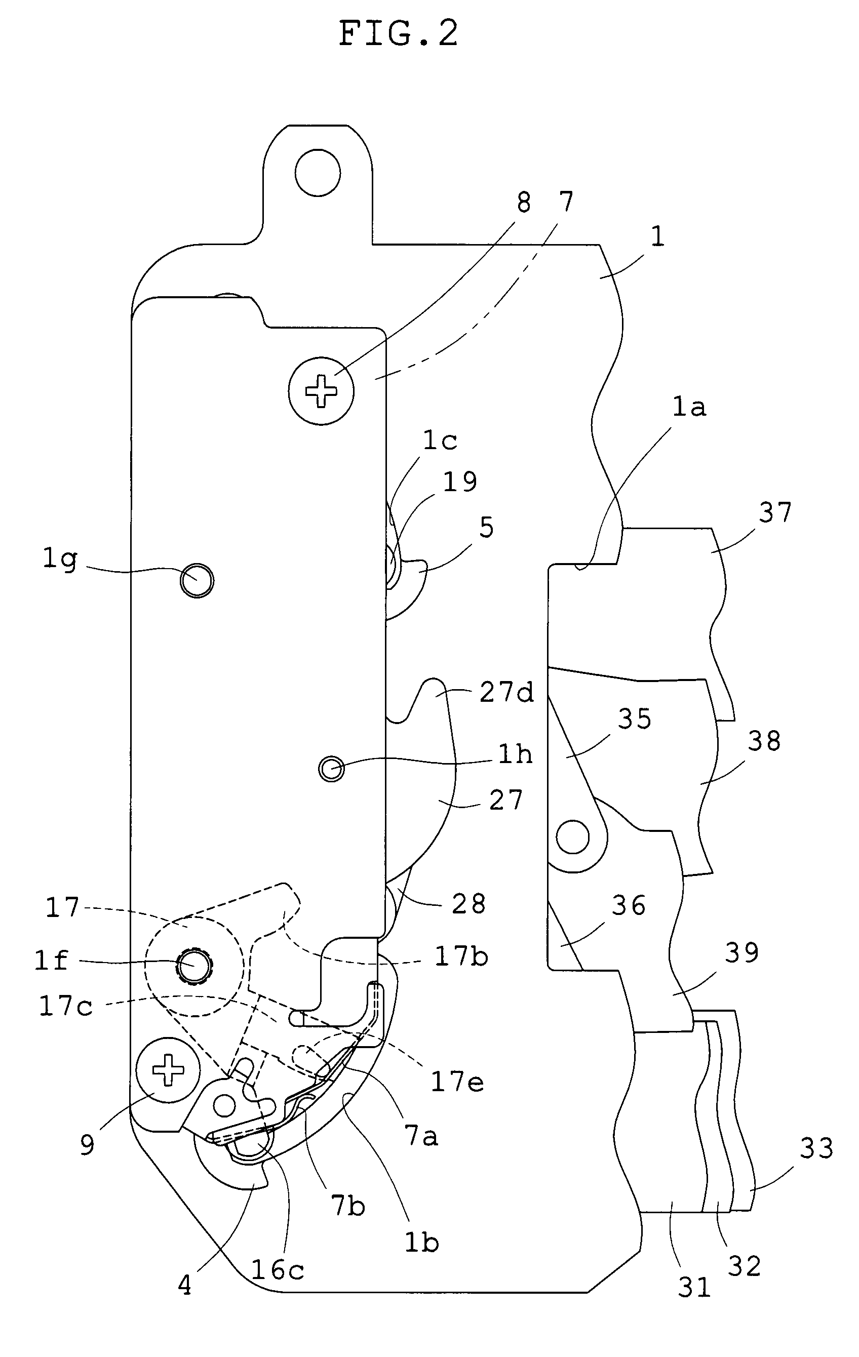
[0035]FIG. 1 is a plan view showing Embodiment 1 of the focal plane shutter for digital cameras of the present invention incorporated in a camera, viewed from the object side, in which the contour of a printed wiring board is indicated by a two-dotted chain line to facilitate a comprehension of a state immediately after the exposure operation of components is completed, and FIG. 2 is a plan view showing the printed wiring board and a switch mechanism attached thereto by enlarging a part of FIG. 1. FIG. 3 is a plan view showing Embodiment 1 by enlarging a part of FIG. 1. FIG. 4 is a sectional view showing the shutter viewed from the right side of FIGS. 2 and 3 to facilitate the comprehension of the overlapping relation of components. FIGS. 5-11 are plan views showing only main components necessary for the explanation of actuation of components of FIG. 3. FIG. 5 shows a state immediately after the completion of the exposure operation as in FIG. 3. FIG. 6 shows a state of the initial s...
embodiment 2
[0074]Subsequently, Embodiment 2 will be explained. FIG. 13, like FIG. 3, is a plan view showing a state immediate after the completion of the exposure operation, and the second driving member 17 for the first blade is shown without cutting the mounting portion 17c. FIG. 14 is a sectional view showing the shutter viewed from the right side of FIG. 13 to facilitate the comprehension of the overlapping relation of components. The structure of FIG. 2 used for the explanation of Embodiment 1 is also used for the explanation of Embodiment 2, except for the restraining member 28. FIG. 12 used for the description of the operation of the Embodiment 1 is also used for that of Embodiment 2. In Embodiment 2, most of components are identical with the components of Embodiment 1. In FIGS. 13 and 14, like numerals are used for like members and parts with respect to Embodiment 1. Thus, in a structural description described below, reference is chiefly made to structures different from Embodiment 1.
[...
PUM
 Abstract
Description
Claims
Application Information
 - R&D
- Intellectual Property
- Life Sciences
- Materials
- Tech Scout
- Unparalleled Data Quality
- Higher Quality Content
- 60% Fewer Hallucinations
Browse by: Latest US Patents, China's latest patents, Technical Efficacy Thesaurus, Application Domain, Technology Topic, Popular Technical Reports.
© 2025 PatSnap. All rights reserved.Legal|Privacy policy|Modern Slavery Act Transparency Statement|Sitemap|About US| Contact US: help@patsnap.com


