Implantable medical device detachment system and methods of using the same

a medical device and detachment system technology, applied in the field of interventional medical device systems, can solve the problems of reducing the service life affecting the operation efficiency of the detachment system,

Active Publication Date: 2008-04-24
CODMAN & SHURTLEFF INC
View PDF32 Cites 81 Cited by
  • Summary
  • Abstract
  • Description
  • Claims
  • Application Information

AI Technical Summary

Benefits of technology

[0009]According to another embodiment or aspect of the present invention, a method of deploying an implantable medical device to a detachment system includes providing a generally hollow tubular carrier member. The carrier member has a distal end with a compressible portion in a compressed condition. An engagement member associated with the distal end is releasably connected to an implantable medical device. The thusly provided system is introduced into a body vessel and the implantable medical device is positioned generally adjacent to a target location of the vessel. When the implantable medical device is properly positioned, it is disengaged from the engagement member, which causes the compressible portion of the carrier member to axially elongate and actively deploy the implantable medical device.

Problems solved by technology

Due to the delicate tissue surrounding cranial blood vessels, especially for example brain tissue, it is very difficult and often risky to perform surgical procedures to treat defects of the cranial blood vessels.
Some of the problems that have been associated with these procedures relate to ensuring the complete release and deployment of the coil.
However, the system does not include any positive means for separating the disengaged clasps from each other, so merely retracting the control wire does not ensure release and deployment of the coil.
Numerous other detachment systems currently in use suffer from similar problems.

Method used


Image

  • Implantable medical device detachment system and methods of using the same
  • Implantable medical device detachment system and methods of using the same
  • Implantable medical device detachment system and methods of using the same

Examples


Embodiment Construction

[0024]As required, detailed embodiments of the present invention are disclosed herein; however, it is to be understood that the disclosed embodiments are merely exemplary of the invention, which may be embodied in various forms. Therefore, specific details disclosed herein are not to be interpreted as limiting, but merely as a basis for the claims and as a representative basis for teaching one skilled in the art to variously employ the present invention in virtually any appropriate manner.

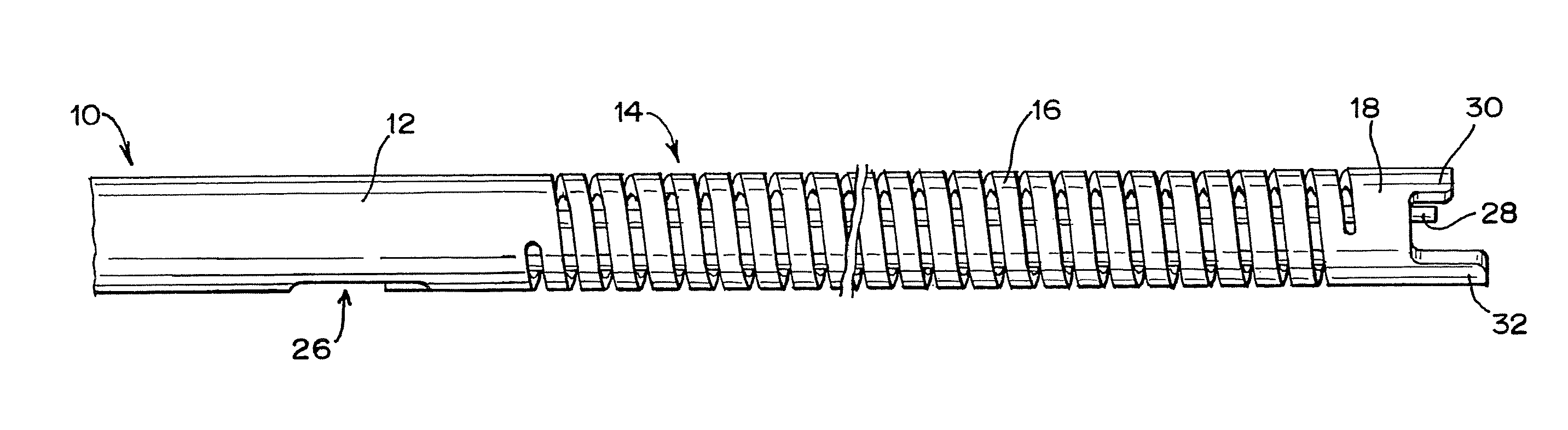
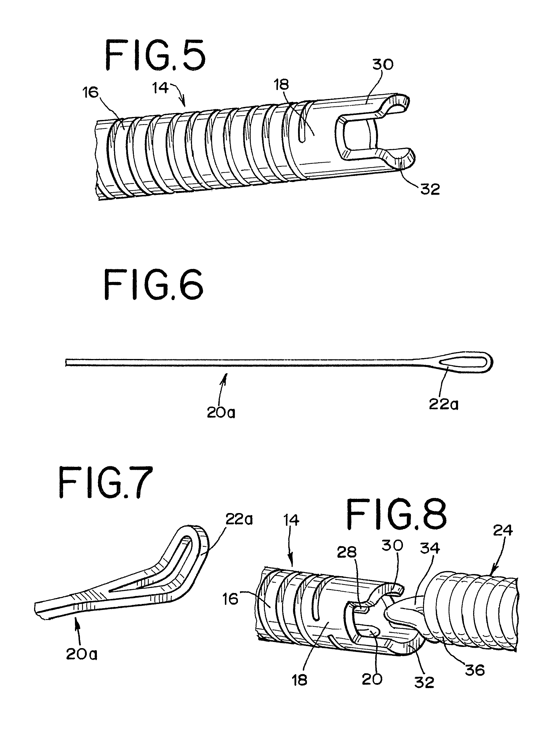
[0025]FIGS. 1-4 illustrate a distal portion of a generally hollow or tubular structure according to the present invention. When used herein, the terms “tubular” and “tube” are to be construed broadly and are not limited to a structure that is a right cylinder or strictly circumferential in cross-section or of a uniform cross-section throughout its length. For example, the tubular structure or system is generally designated at 10 and shown as a substantially right cylindrical structure. However, the...


PUM

PropertyMeasurementUnit
diameteraaaaaaaaaa
diameteraaaaaaaaaa
diameteraaaaaaaaaa

Abstract

An implantable medical device detachment system is provided with a carrier member having a compressible portion at a distal end thereof. The compressible portion is moved to a compressed condition to allow an engagement member of the system to releasably engage an implantable device, such as an embolic coil. The carrier member and associated implantable device are fed through a body vessel to a target location, where the device is disengaged from the engagement member. The compressible portion then moves from the compressed condition to an elongated condition to completely separate the implantable device from the engagement member.

Description

FIELD OF THE INVENTION[0001]This invention generally relates to interventional medical device systems that are navigable through body vessels of a human subject. More particularly, this invention relates to detachment systems for deploying an implantable medical device to a target location of a body vessel and methods of using the same.DESCRIPTION OF RELATED ART[0002]The use of catheter delivery systems for positioning and deploying therapeutic devices, such as dilation balloons, stents and embolic coils, in the vasculature of the human body has become a standard procedure for treating endovascular diseases. It has been found that such devices are particularly useful in treating areas where traditional operational procedures are impossible or pose a great risk to the patient, for example in the treatment of aneurysms in cranial blood vessels. Due to the delicate tissue surrounding cranial blood vessels, especially for example brain tissue, it is very difficult and often risky to per...

Claims


Application Information

Patent Timeline
Patent Type & Authority Applications(United States)
IPC IPC(8): A61M37/00
CPCA61F2/95Y10T29/49826A61F2002/9511A61F2002/9505A61B2017/12054
Inventor MITELBERG, VLADIMIRTHINNES, JOHN H.BALGOBIN, KEITH
Owner CODMAN & SHURTLEFF INC
Why Eureka
Try Eureka