Wiper Blade

Active Publication Date: 2008-05-01
MITSUBA CORP
View PDF9 Cites 74 Cited by
  • Summary
  • Abstract
  • Description
  • Claims
  • Application Information

AI Technical Summary

Benefits of technology

[0021]According to the present invention, since the cover is provided so as to be aligned with the rubber holder in the longitudinal direction thereof, the entire longitudinal-directional portion of the blade rubber can be covered with the rubber holder and the covers. Therefore, the attaching groove to be mounted on the leaf-spring member, burrs occurring in molding the blade rubber, or the like can be concealed so that fine appearance can be improved. Especially, the rubber holder is formed so as to have a U-shaped cross section, so that the wiper blade can be formed into a shape with a sense of unity.
[0022]According to the present invention, a plurality of kinds of covers different in length dimension are used, so that the same kind of rubber holders can be shared with a plurality of kinds of blade rubbers dif

Problems solved by technology

Therefore, burrs or the like occurring when the attaching groove on which the leaf-spring member is mounted or when the blade r

Method used


Image

  • Wiper Blade
  • Wiper Blade
  • Wiper Blade

Examples


Example

[0051]Embodiments of the present invention will be described below in detail with reference to the drawings.

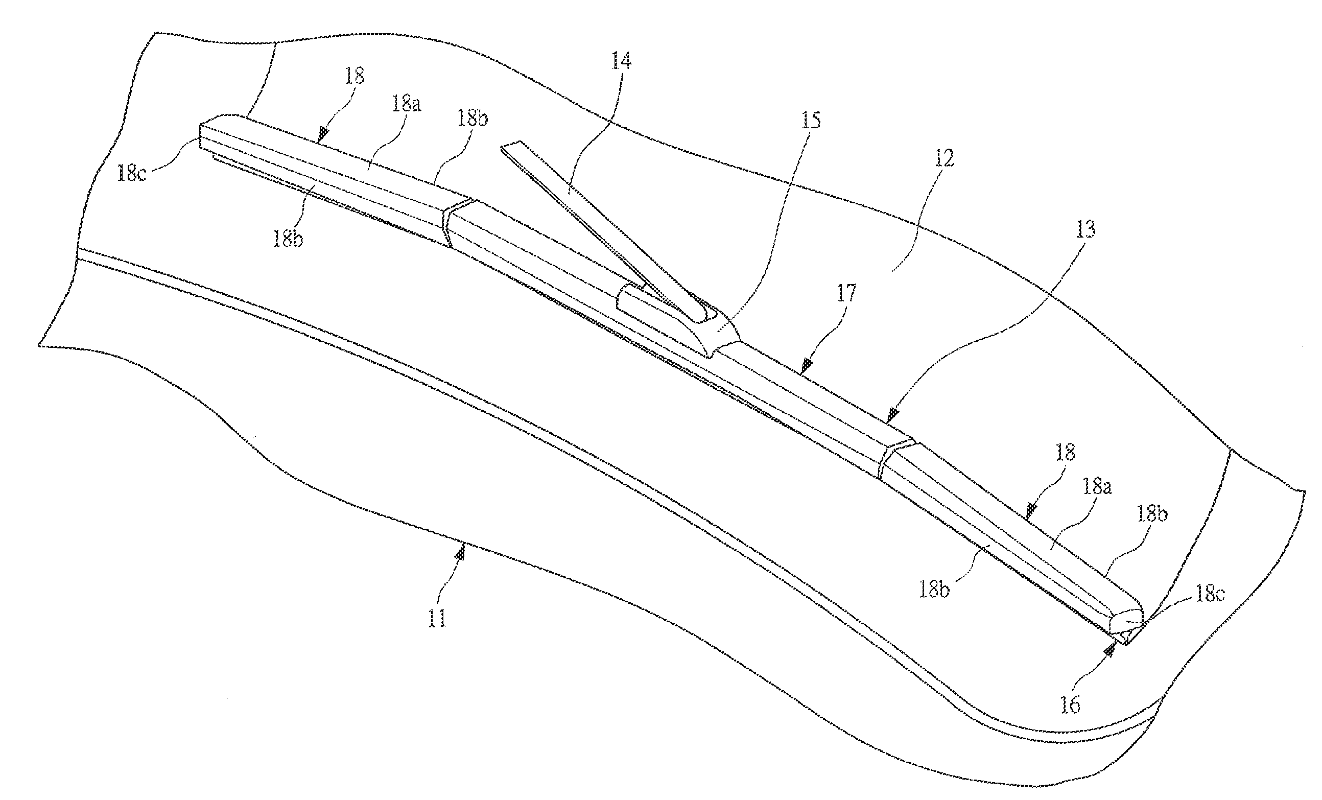
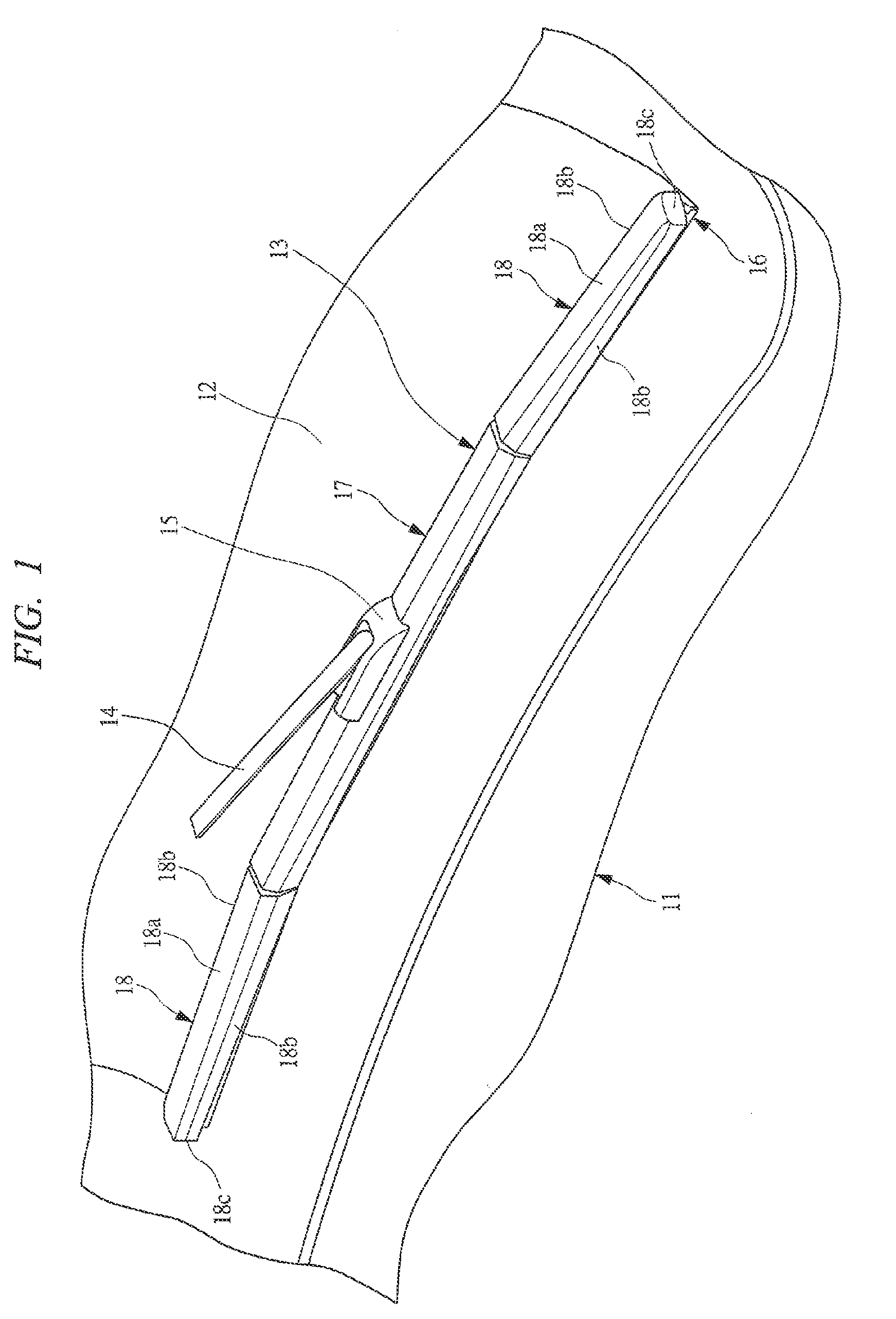
[0052]A vehicle 11 shown in FIG. 1 is provided with a wiper blade 13 for wiping adhesion matters such as rain water or droplets from a preceding car adhering to a front windshield glass 12 (hereinafter called “windshield glass 12”). The wiper blade 13 is attached via an attaching portion 15 to a tip of a wiper arm 14 swingably provided on the vehicle 11, so that when the wiper arm 14 is driven by an unshown wiper motor, the wiper blade 13 together with the wiper arm 14 carries out swinging movement on the windshield glass 12 to wipe the windshield glass 12.

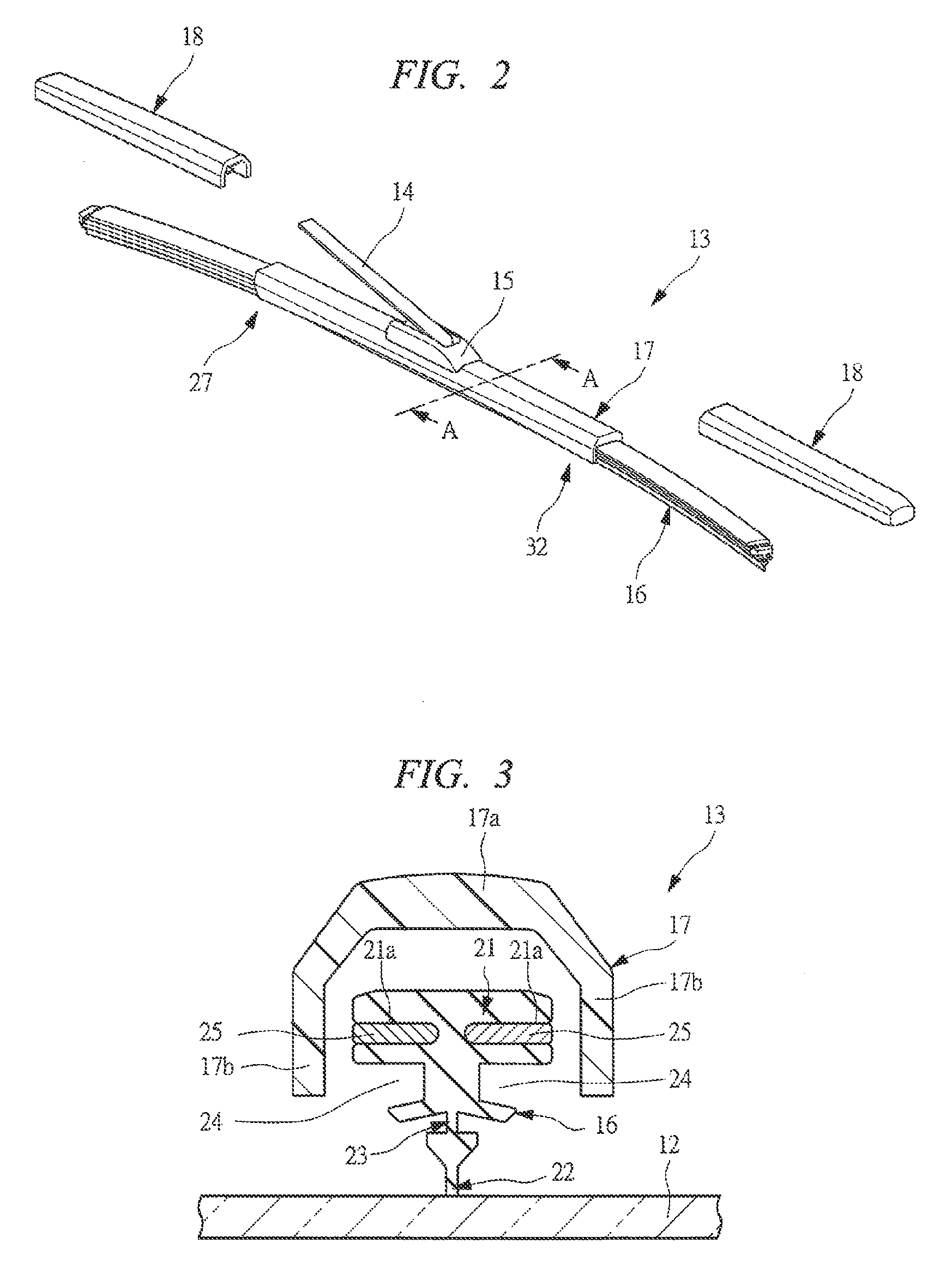
[0053]FIG. 2 is a perspective view showing a state of removing a cover of the wiper blade shown in FIG. 1. As understood from FIG. 2, the wiper blade 13 has a structure in which a blade rubber 16 contacting with the windshield glass 12 is held by a rubber holder 17. Also, a pair of covers 18 are provided on both side portion...


PUM


Abstract

A wiper blade 13 comprises a rubber holder 17 attached to a tip of a wiper arm 14 and a blade rubber 16 supported by the rubber holder 17. The rubber holder 17 is formed into a U-shaped cross section, and an intermediate portion of the blade rubber 16 is covered with the rubber holder 17. Also, both sides of the rubber holder 17 are provided with covers 18 in a longitudinal direction in series. Each of the cover 18 becomes rotatable to the rubber holder 17 in a direction perpendicular to a front windshield glass 12, and exposed portions from the rubber holder 17 of the blade rubber 16 are covered with these covers 18 in an elastically deformable state.

Description

CROSS REFERENCE TO RELATED APPLICATIONS[0001]This application is entitled to the benefit of and incorporates by reference essential subject matter disclosed in International Patent Application No. PCT / JP2005 / 020040 filed on Oct. 31, 2005 and Japanese Patent Application No. 2004-325347 filed Nov. 9, 2004.TECHNICAL FIELD[0002]The present invention relates to a wiper blade that wipes a windshield glass of a vehicle.BACKGROUND ART[0003]A vehicle such as a passenger car, a bus, and a truck is provided with a wiper blade for wiping rain, snow, insects, droplets from a preceding vehicle, or the like adhering to on a front windshield glass or rear windshield glass to ensure a view of a driver. Such a wiper blade has a rubber holder attached to a tip of a wiper arm of the vehicle and a rubber-made blade rubber held by the rubber holder, so that when the wiper arm is driven by a wiper motor, the wiper blade reciprocates within a wiping range on a windshield glass to wipe a glass face.[0004]In...

Claims


Application Information

Patent Timeline
IPC IPC(8): B60S1/38
CPCB60S1/3801B60S1/381B60S2001/3822B60S1/3896B60S2001/3815B60S1/3887
Inventor MACHIDA, KENFUJIWARA, MASARUABE, JUN
Owner MITSUBA CORP
Why Eureka
Try Eureka