Gripping device for articulated work machine

Active Publication Date: 2013-07-11
BLUE LEAF I P
View PDF5 Cites 0 Cited by
  • Summary
  • Abstract
  • Description
  • Claims
  • Application Information

AI Technical Summary

Benefits of technology

The present patent text describes a device that allows work machines to move in different directions. One advantage of this device is that it can be used with a variety of work machines. Another advantage is that it is an affordable tool used in the operation of articulating work machines.

Problems solved by technology

Additionally, applications associated with abrasive objects can “wear out” the teeth, possibly requiring replacement of the dipper arm.

Method used


Image

  • Gripping device for articulated work machine
  • Gripping device for articulated work machine
  • Gripping device for articulated work machine

Examples


Embodiment Construction

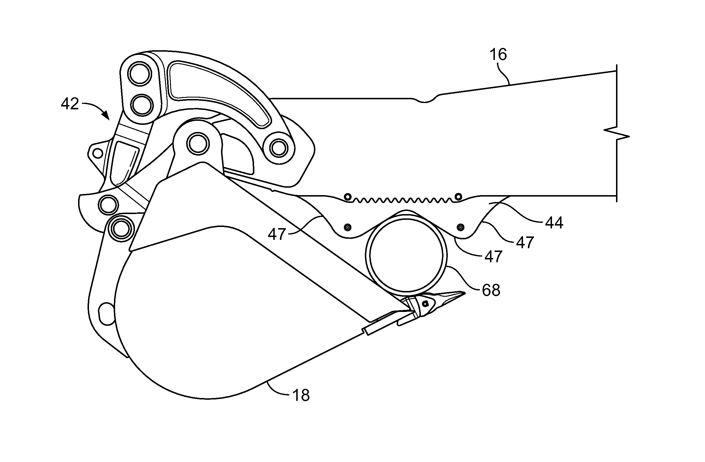
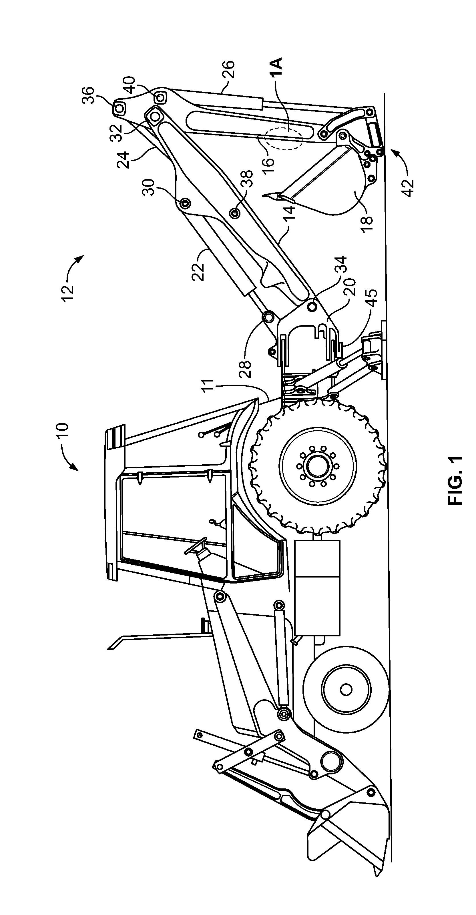
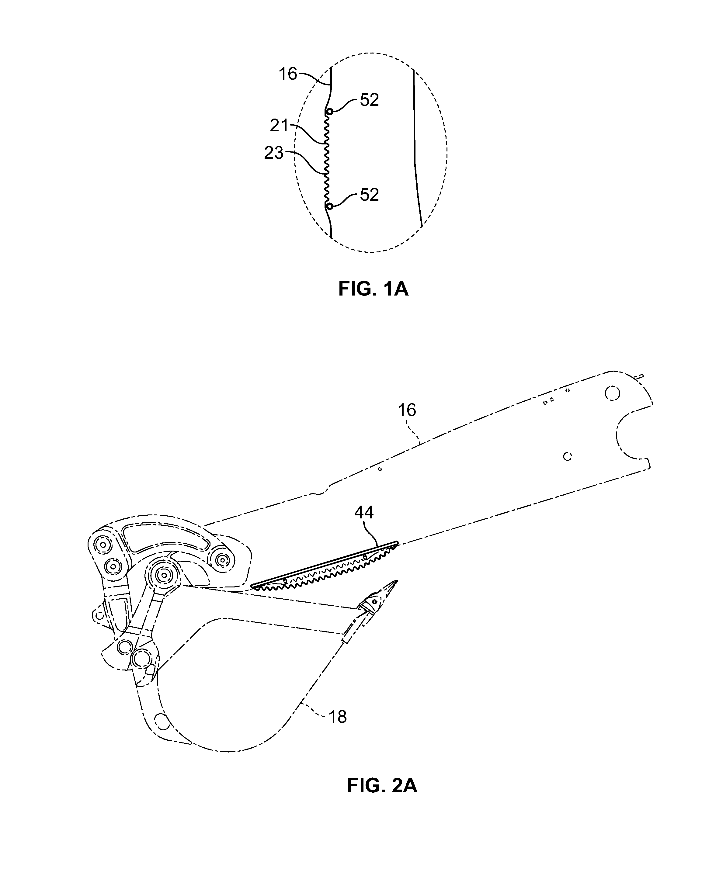
[0021]Referring to the drawings for a description of an articulated earthworking machine 10, sometimes referred to as an excavator, that employs the present disclosure, FIG. 1 shows a third portion or boom 14 in a lowered position. Boom 14 pivots about a pivot joint 34 and coincident pivot axis of a second portion or swing frame or frame 20 and is controlled by extension / contraction of a fluid ram 22 connected between pivot joints 28, 30. Frame 20 pivots about a pivot joint 45 with respect to a first portion or base frame 11 of the machine. Similarly, an arm 16, often referred to as a dipper, pivots about pivot joint 32 of boom 14 and is controlled by extension / contraction of fluid ram 24 connected between pivot joints 36, 38. In addition, attachment or implement 18, such as a bucket, is pivotably connected to arm 16 and is controlled by extension / contraction of a fluid ram 26 connected between pivot joint 40 and interconnected linkages 42. A backhoe 12 comprises the combination of ...


PUM


Abstract

A work machine includes a pivotable arm having a first gripping device formed therein, the arm operatively connected to an attachment for securing an object between the first gripping device and the attachment. A second gripping device is removably securable to the arm near the first gripping device, the second gripping device configured to at least partially secure an object between the second gripping device and the attachment.

Description

FIELD OF THE DISCLOSURE[0001]The present disclosure relates generally to the field of work machines. It relates more particularly to articulated work machines.BACKGROUND OF THE DISCLOSURE[0002]Articulated work machines, such as a loader backhoe, also referred to as a backhoe, are commonly used on job sites. The backhoe may be used to manipulate an object by securing the object between a dipper arm and an attachment, such as a bucket. Teeth formed along an edge of the dipper arm can assist with this task. However, there can be shortcomings associated with the formed teeth. For example, the formed teeth pattern, having a triangular profile similar to that of a saw blade may work well for certain applications, but not others, such as manipulation of metal pipes, in which the teeth may cause damage to the pipe. Additionally, applications associated with abrasive objects can “wear out” the teeth, possibly requiring replacement of the dipper arm.[0003]Accordingly, there is an unmet need t...

Claims


Application Information

Patent Timeline
IPC IPC(8): B66C1/42E02F3/96
CPCE02F3/38E02F3/404E02F3/364
Inventor BRADLEY, NATHANHENNEMANN, MATTHEW J.HEIAR, MICHAEL R.O'CONNOR, BRADLEYSANNING, DAVID J.WAGENBACH, MATTHEW
Owner BLUE LEAF I P
Why Eureka
Try Eureka