Turbofan engine assembly and method of assembling same

a technology of turbine engines and components, applied in the direction of machines/engines, marine propulsion, vessel construction, etc., can solve the problems of overall weight, design complexity, and/or manufacturing costs of such engines, and achieve the effect of increasing the overall weight, design complexity and manufacturing costs

Inactive Publication Date: 2008-05-01
GENERAL ELECTRIC CO
View PDF16 Cites 70 Cited by
  • Summary
  • Abstract
  • Description
  • Claims
  • Application Information

AI Technical Summary

Benefits of technology

[0003]In one aspect, a method of assembling a turbofan engine assembly is provided. The method includes providing a core gas turbine engine including a high-pressure compressor, a combustor, and a high-pressure turbine, coupling a booster compressor upstream from the core gas turbine engine, coupling a intermediate-pressure turbine downstream from the core gas turbine engine, coupling the booster compressor to the intermediate...

Problems solved by technology

However, while the use of a counter-rotating low-pressure turbine increases the overall engine effi...

Method used


Image

  • Turbofan engine assembly and method of assembling same
  • Turbofan engine assembly and method of assembling same
  • Turbofan engine assembly and method of assembling same

Examples


Embodiment Construction

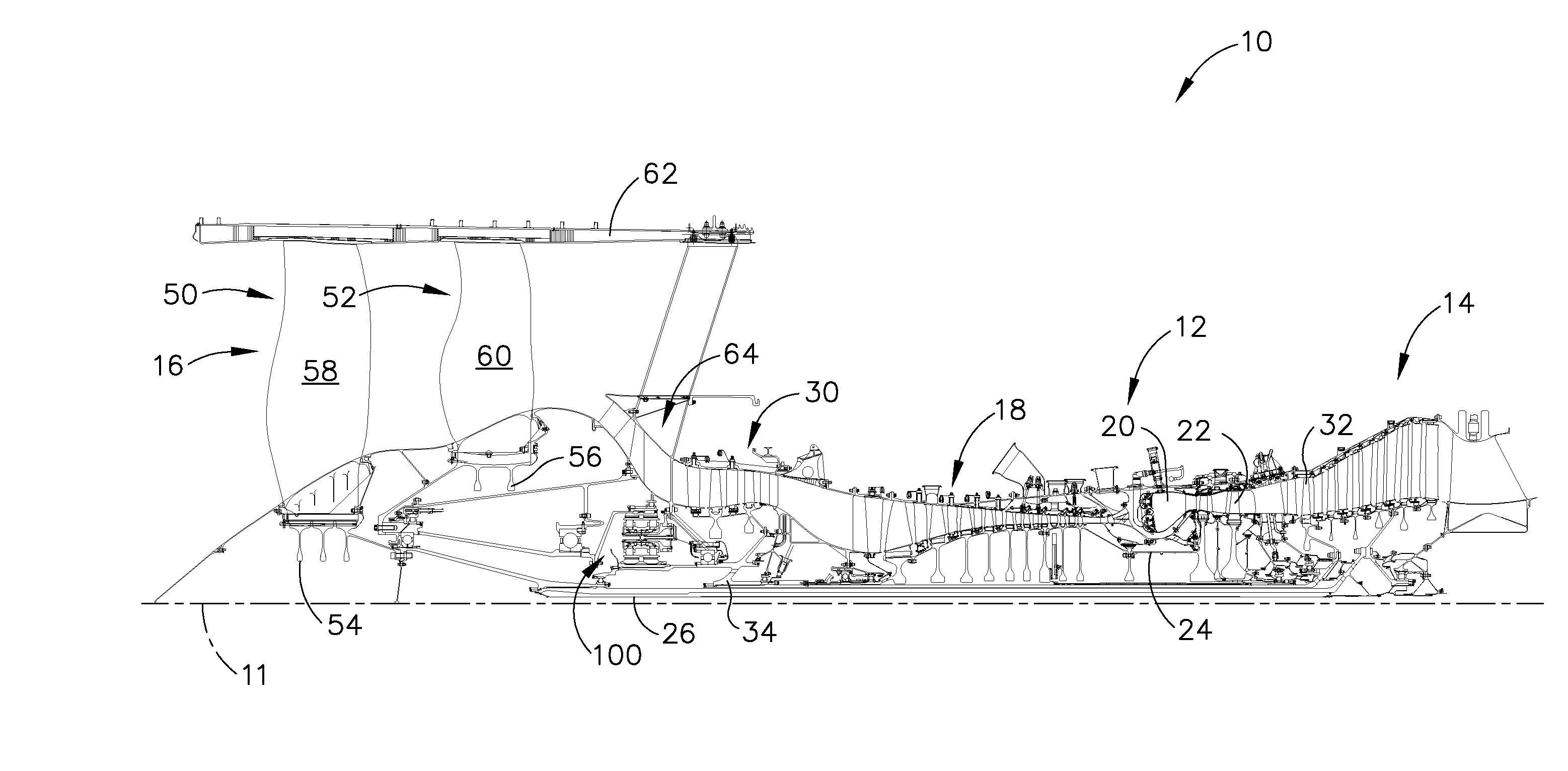
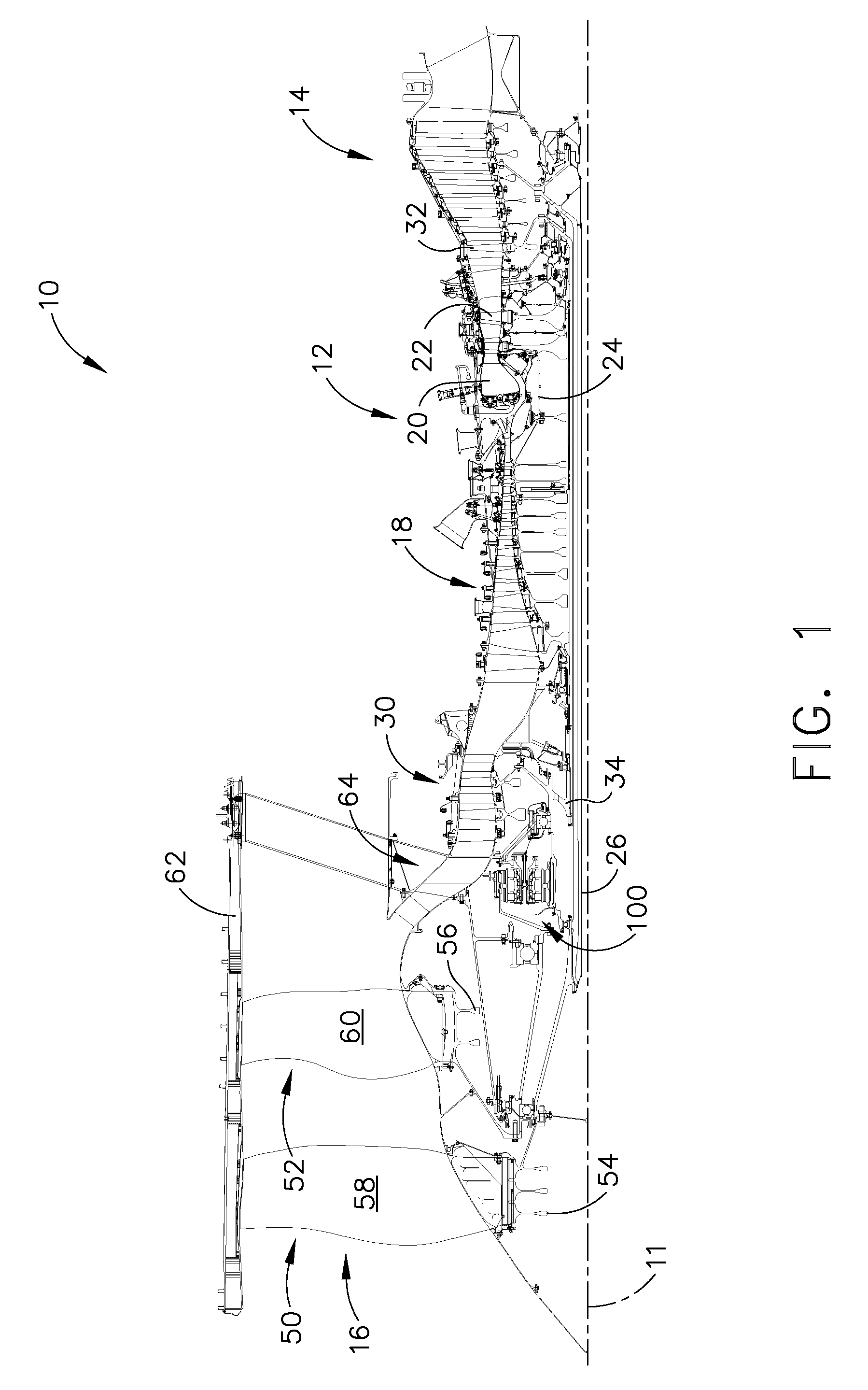
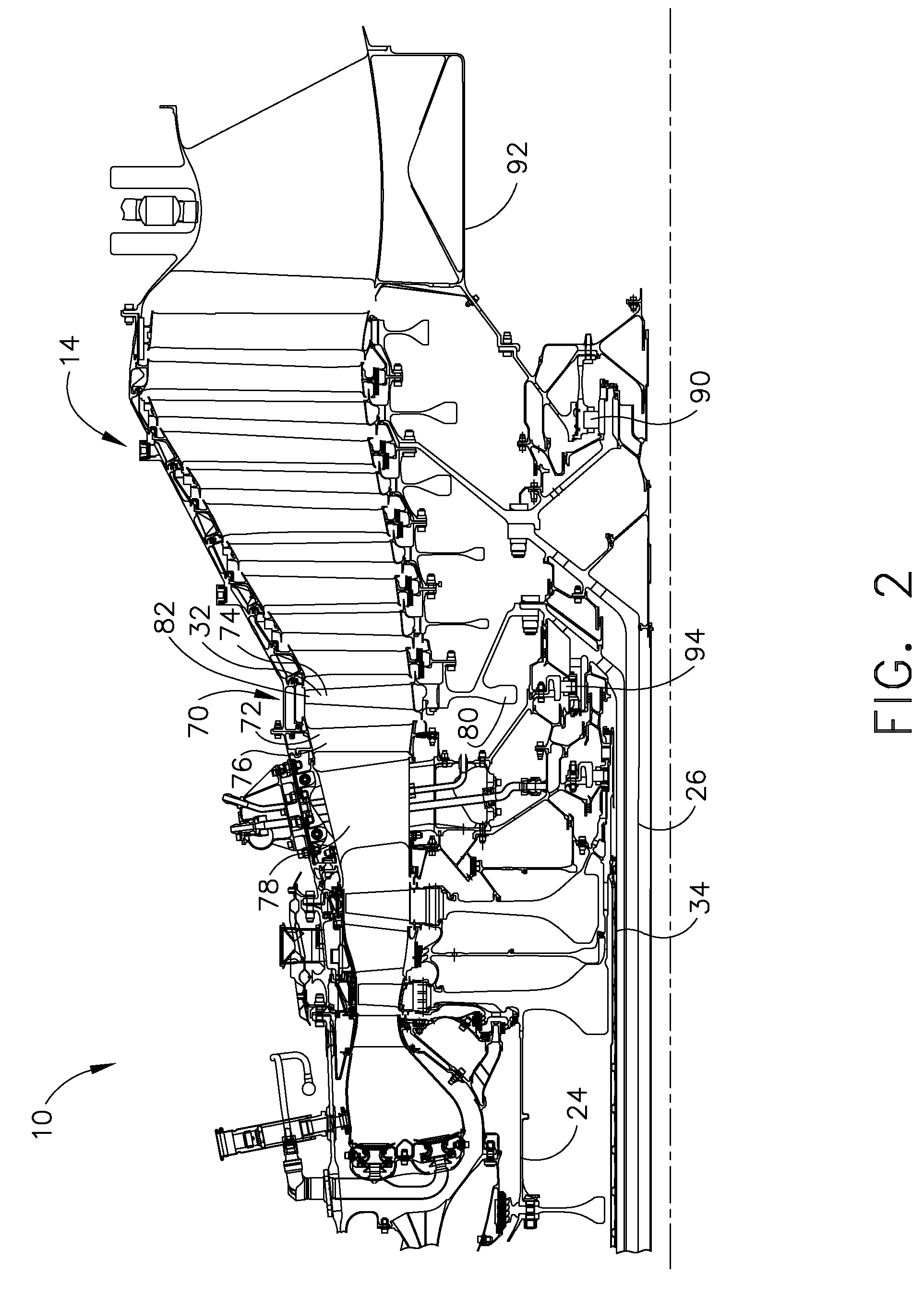
[0009]FIG. 1 is a cross-sectional view of a portion of an exemplary turbofan engine assembly 10 having a longitudinal axis 11. In the exemplary embodiment, turbofan engine assembly 10 includes a core gas turbine engine 12, a low-pressure turbine 14 disposed axially downstream from core gas turbine engine 12 and a counter-rotating fan assembly 16 that is disposed axially upstream from core gas turbine engine 12. Core gas turbine engine 12 includes a high-pressure compressor 18, a combustor 20, and a high-pressure turbine 22 that is coupled to high-pressure compressor 18 via a shaft 24. In the exemplary embodiment, high-pressure turbine 22 includes two turbine stages. Optionally, high-pressure turbine 22 may include a single stage or have a stage count greater than two.

[0010]In the exemplary embodiment, counter-rotating fan assembly 16 includes a first or forward fan assembly 50 and a second or an aft fan assembly 52 that is disposed downstream from forward fan assembly 50. The terms ...


PUM


Abstract

A turbofan engine assembly includes a core gas turbine engine including a high-pressure compressor, a combustor, and a high-pressure turbine, a booster compressor coupled upstream from the core gas turbine engine, an intermediate-pressure turbine coupled to the booster compressor, the intermediate-pressure turbine disposed downstream from the core gas turbine engine, a counter-rotating fan assembly disposed upstream from the booster compressor, the counter-rotating fan assembly comprising a first fan configured to rotate in a first direction and a second fan configured to rotate in an opposite second direction, and an intermediate-pressure turbine disposed downstream from the core gas turbine engine, wherein the intermediate-pressure turbine drives the booster compressor and the second fan assembly. A method of assembling the above turbofan engine assembly is also described herein.

Description

BACKGROUND OF THE INVENTION[0001]This invention relates generally to gas turbine engines, and more specifically to turbofan engine assembly that includes a booster compressor driven by an intermediate-pressure turbine.[0002]To facilitate increasing engine efficiency, at least one known turbofan assembly includes a counter-rotating low-pressure turbine that is coupled to a counter-rotating fan assembly. More specifically, to assemble a turbofan engine assembly that includes a counter-rotating low-pressure turbine, an outer rotating spool, a rotating frame, a mid-turbine frame, and two concentric shafts, are installed within the turbofan engine assembly to facilitate supporting the counter-rotating low-pressure turbine. However, while the use of a counter-rotating low-pressure turbine increases the overall engine efficiency, the overall weight, design complexity, and / or manufacturing costs of such an engine are increased.BRIEF DESCRIPTION OF THE INVENTION[0003]In one aspect, a method ...

Claims


Application Information

Patent Timeline
IPC IPC(8): F02K3/02
CPCF02C7/36F02K3/072F01D25/16
Inventor ORLANDO, ROBERT JOSEPHMONIZ, THOMAS ORY
Owner GENERAL ELECTRIC CO
Why Eureka
Try Eureka