Dynamic sealing assembly to accommodate differential thermal growth of fuel injector components

a technology of differential thermal growth and sealing assembly, which is applied in the direction of mechanical equipment, machines/engines, light and heating equipment, etc., can solve the problems of significant cost associated with the formation of helically coiled fuel tubes

Active Publication Date: 2008-05-01
COLLINS ENGINE NOZZLES INC
View PDF8 Cites 16 Cited by
  • Summary
  • Abstract
  • Description
  • Claims
  • Application Information

AI Technical Summary

Benefits of technology

[0011]Preferably, the dynamic sealing member is an O-ring type seal and is retained in an annular seal retention channel formed between two axially spaced apart annular flanges associated with an upper end portion of the adapter. Each annular flange of the adapter includes a first annular flange

Problems solved by technology

These stress concentrations can lead to the formation and propagation of cracks, eventually leading to fuel leaks, resulting in injector failures.
Those skilled in the art will readily appreciate t

Method used


Image

  • Dynamic sealing assembly to accommodate differential thermal growth of fuel injector components
  • Dynamic sealing assembly to accommodate differential thermal growth of fuel injector components
  • Dynamic sealing assembly to accommodate differential thermal growth of fuel injector components

Examples


Embodiment Construction

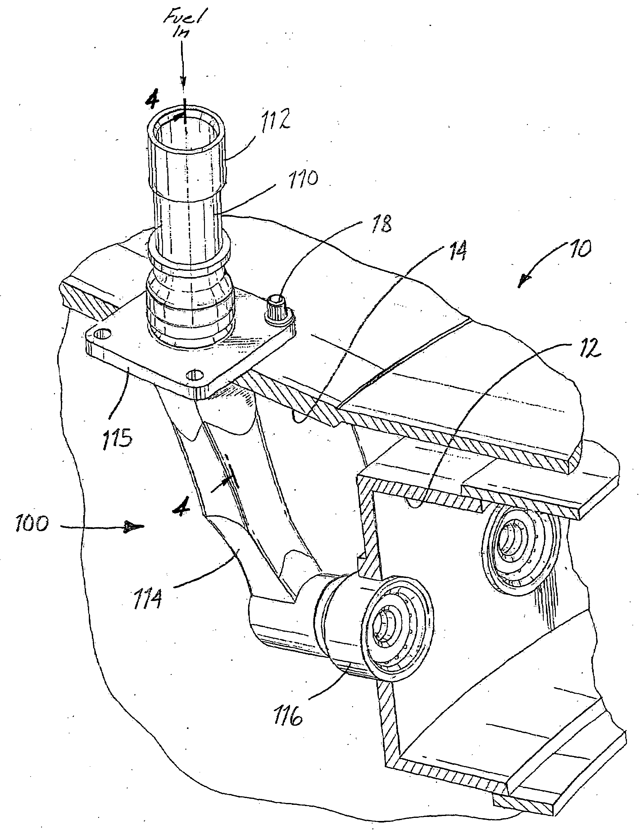
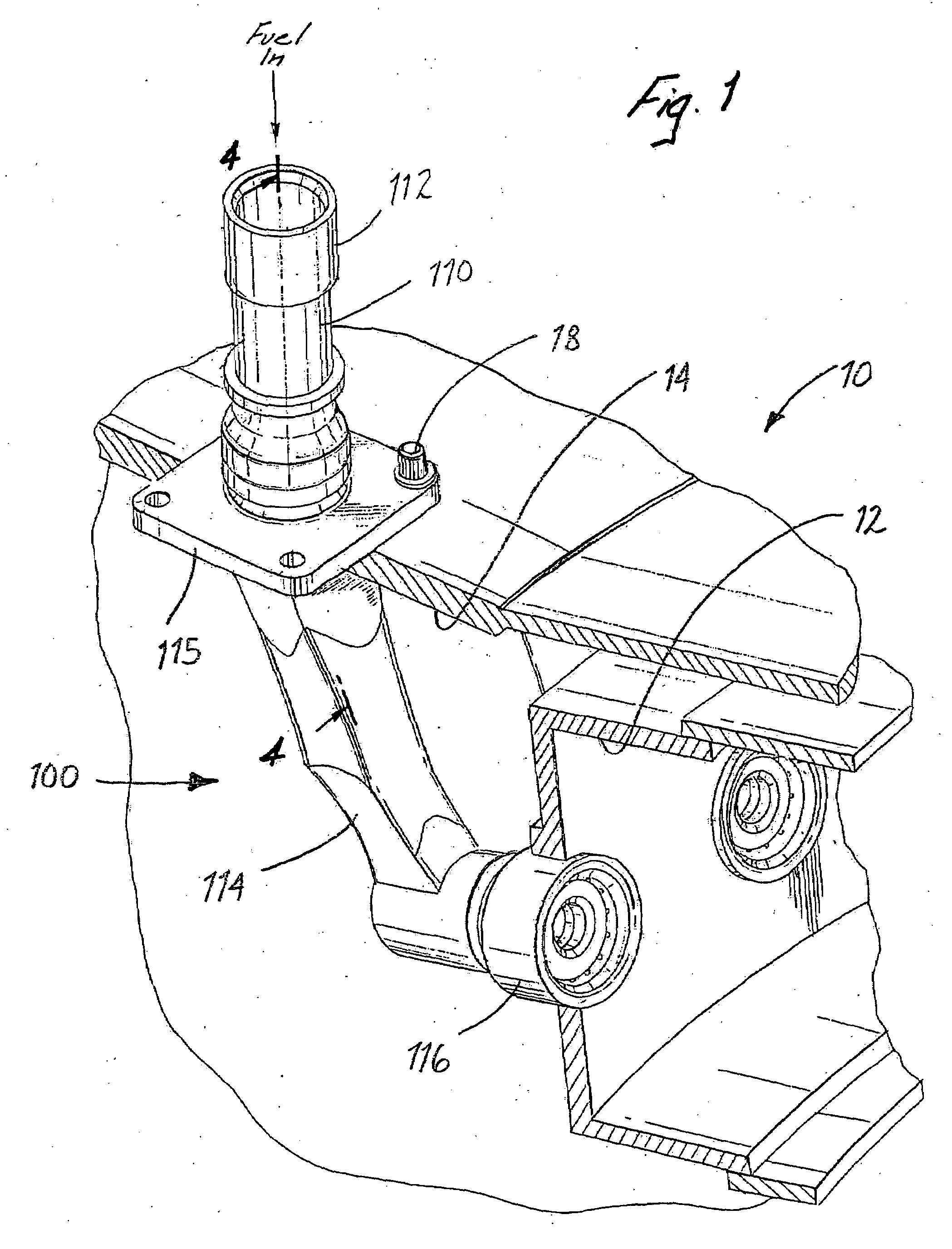
[0031]Referring now to the drawings wherein like reference numerals identify similar features or elements of the various embodiments of the dynamic sealing assemblies of the subject invention disclosed herein, there is illustrated in FIG. 1 a fuel injector constructed in accordance with a preferred embodiment of the subject invention and designated generally by reference numeral 100.

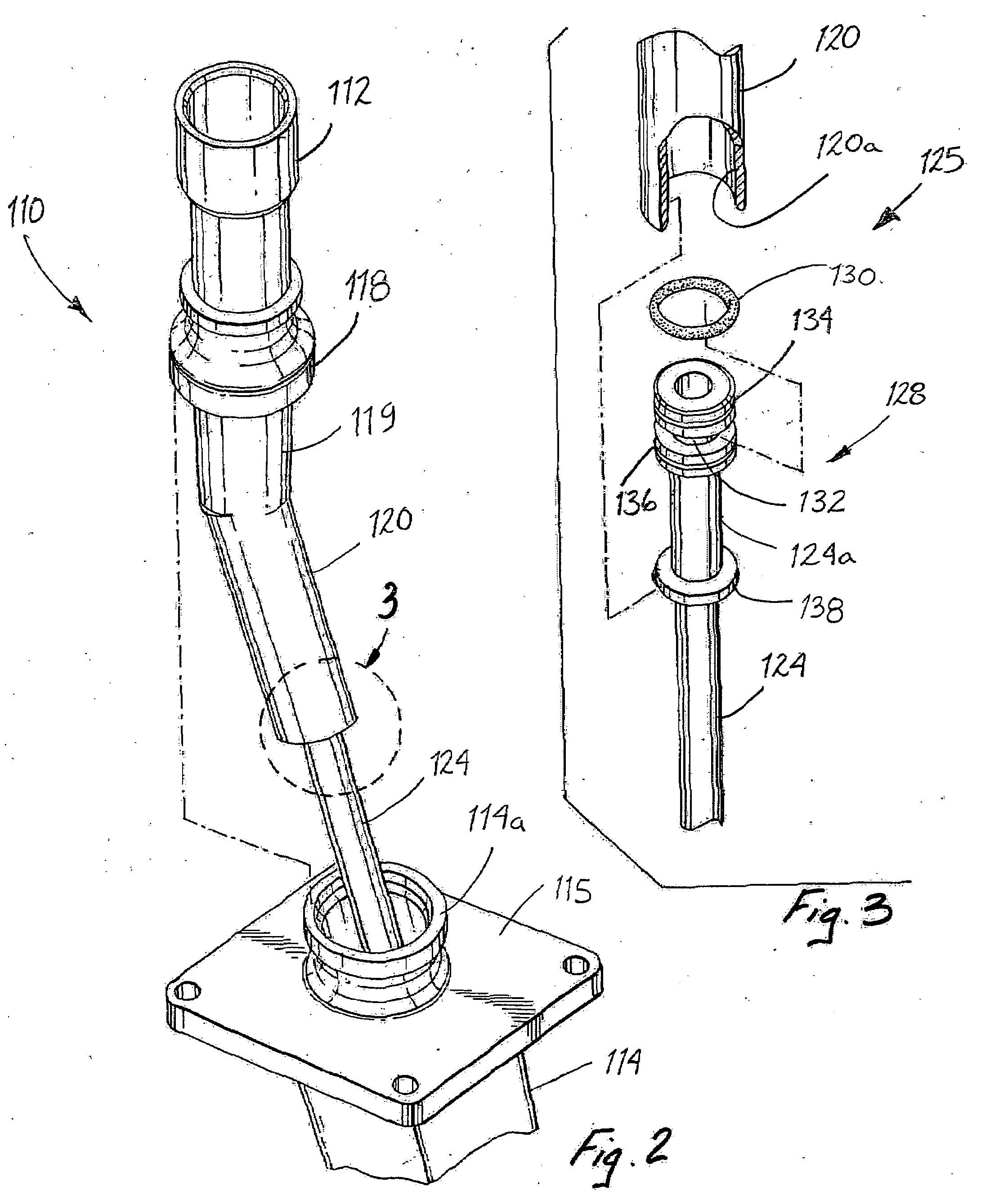
[0032]Fuel injector 100 is adapted and configured to issue atomized fuel into the combustion chamber 12 of a gas turbine engine 10. In general, fuel injector 100 includes an inlet end portion 110 including a fuel inlet fitting 112 for receiving fuel from a distribution manifold (not shown), an elongated body portion or support strut 114 extending from the inlet end portion 110, and a fuel atomization nozzle 116 for issuing fuel into the combustion chamber 12. A mounting flange 115 is provided at the upper end of the support strut 114 below the fuel inlet fitting 112 for securing the fuel injector 100 to ...


PUM


Abstract

A fuel injector for a gas turbine engine is disclosed which includes an inlet fitting for receiving fuel, a nozzle for issuing fuel into the gas turbine engine, an injector body extending between the inlet fitting and the nozzle and having and interior bore extending therethrough, and an elongated fuel tube disposed within the interior bore of the injector body for delivering fuel from the inlet fitting to the nozzle. The fuel tube has an inlet end portion dynamically associated with the inlet fitting and an outlet end portion rigidly connected to the nozzle. An adapter is operatively associated with either the inlet end section of the fuel tube or a reception bore formed with the inlet fitting of the injector for accommodating a seal member in a manner that permits thermal growth of the injector body relative to the fuel tube.

Description

BACKGROUND OF THE INVENTION[0001]1. Field of the Invention[0002]The subject invention is directed to an apparatus to compensate for differential growth of fuel injector components due to thermal expansion, and more particularly, to an apparatus for accommodating thermal growth of a fuel injector body relative to a fuel delivery tube disposed within the fuel injector body during engine operation.[0003]2. Description of Related Art[0004]Fuel injectors are important components of gas turbine engines and they play a critical role in determining engine performance. A typical fuel injector includes an external support body having an inlet fitting at one end for receiving fuel and an atomizer nozzle at the other end for issuing atomized fuel into the combustor of a gas turbine engine. The inlet fitting is in fluid communication with the atomizer nozzle by way of an internal fuel delivery tube.[0005]During engine operation, the external support body of the fuel injector is surrounded by hig...

Claims


Application Information

Patent Timeline
IPC IPC(8): F02C1/00
CPCF02C7/22F23R3/283F23D2211/00
Inventor HAGGERTY, DANIELHALL, TROY
Owner COLLINS ENGINE NOZZLES INC
Why Eureka
Try Eureka