Eureka AIR delivers breakthrough ideas for toughest innovation challenges, trusted by R&D personnel around the world.

Well flow meter

a flow meter and well technology, applied in the field of flow meters, can solve problems such as surface cracking, land subsidence, and well overdrafts

Inactive Publication Date: 2008-05-01
HUNTSMAN A RUSSELL +1
View PDF11 Cites 10 Cited by
  • Summary
  • Abstract
  • Description
  • Claims
  • Application Information

AI Technical Summary

Problems solved by technology

However, well overdraft may occur when water is removed from a water aquifer at a faster rate than can be naturally replaced by rain or snow.
The lowering of the water table may cause problems such as land subsidence, surface cracking, sinkholes on the surface, damage to the aquifer's water producing character due to compaction.
In the past, private water wells were largely unregulated.
However, the rising demands on water resources, as well as water shortages, have prompted regulatory agencies to step-up their oversight of private water wells.
Both of these types of existing water meters are time-consuming to install and offer little or no protection from flooding and other problems.
Further, the presently available well flow meters are usually constructed by combining existing meters, meter boxes and component parts to create a retrofit unit that is labor intensive and time-consuming to install.
Many of these well flow meters use outdated technology.
Thus, while many regulatory agencies would like to monitor water use derived from underground sources, there is currently not a consistent, convenient and effective system available.
Further complicating the monitoring of water wells is their remote location.
In a given rural area, water wells may be separated by large distances and the wells themselves may be inaccessible for a variety of reasons, including locked access points and uncooperative well owners.

Method used


Image

  • Well flow meter
  • Well flow meter
  • Well flow meter

Examples


Embodiment Construction

[0017] For the purposes of promoting an understanding of the principles in accordance with the disclosure, reference will now be made to the embodiments illustrated in the drawings and specific language will be used to describe the same. It will nevertheless be understood that no limitation of the scope of the disclosure is thereby intended. Any alterations and further modifications of the inventive features illustrated herein, and any additional applications of the principles of the disclosure as illustrated herein, which would normally occur to one skilled in the relevant art and having possession of this disclosure, are to be considered within the scope of the disclosure claimed.

[0018] It must be noted that, as used in this specification and the appended claims, the singular forms “a,”“an,” and “the” include plural referents unless the context clearly dictates otherwise. In describing and claiming the present disclosure, the following terminology will be used in accordance with ...


PUM


Abstract

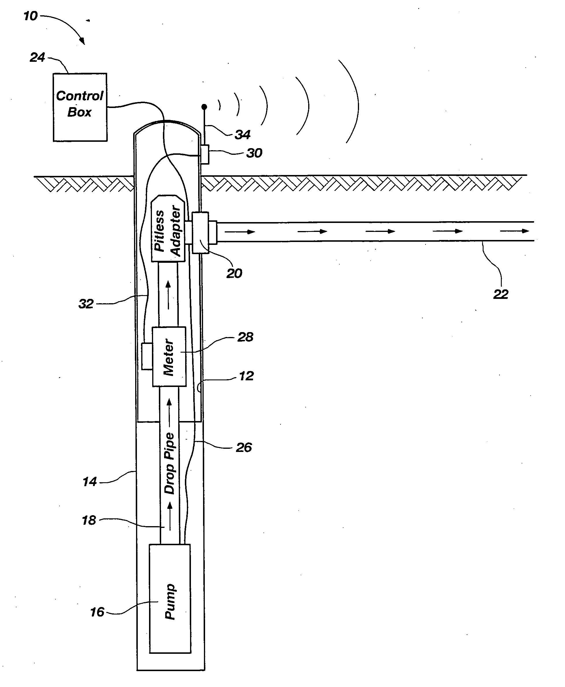
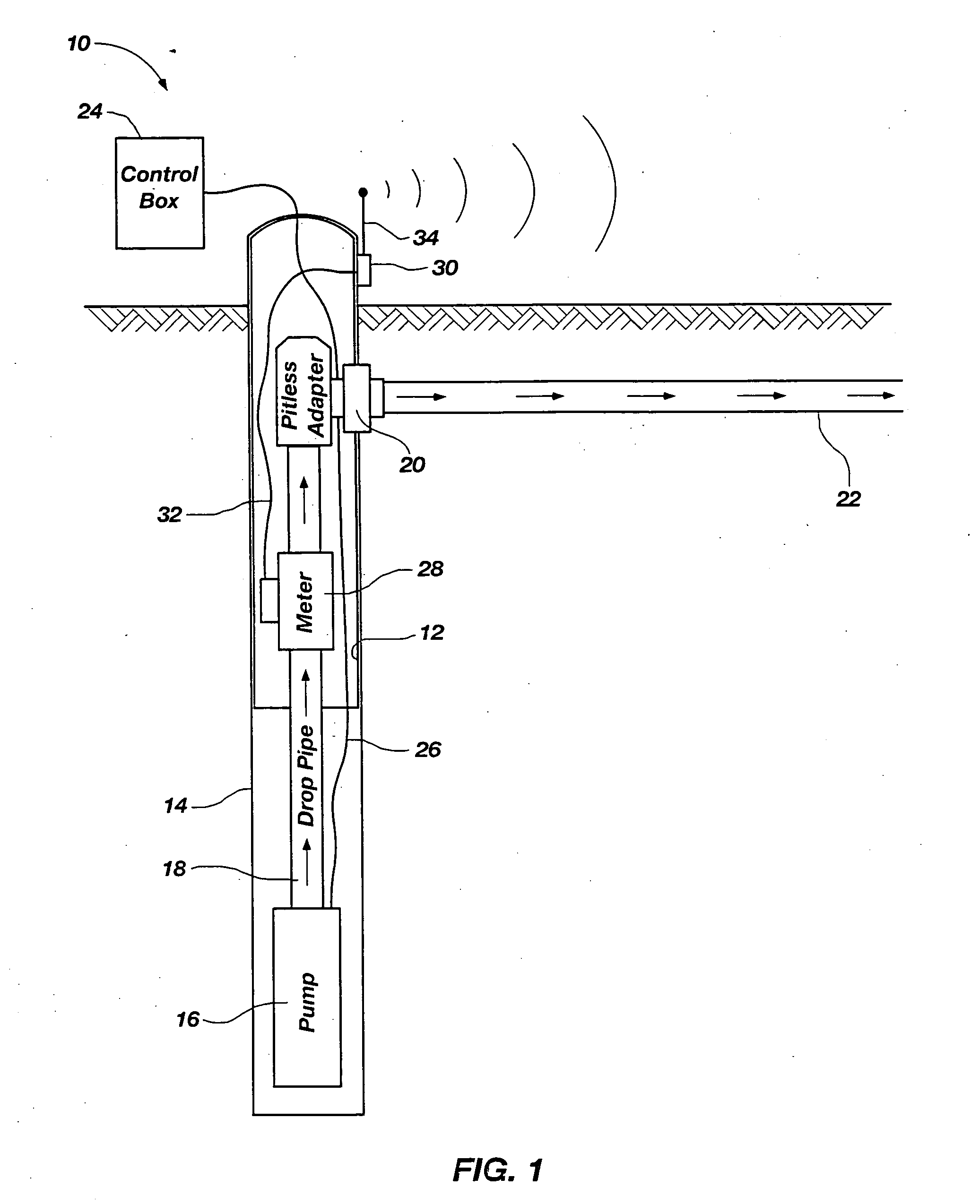
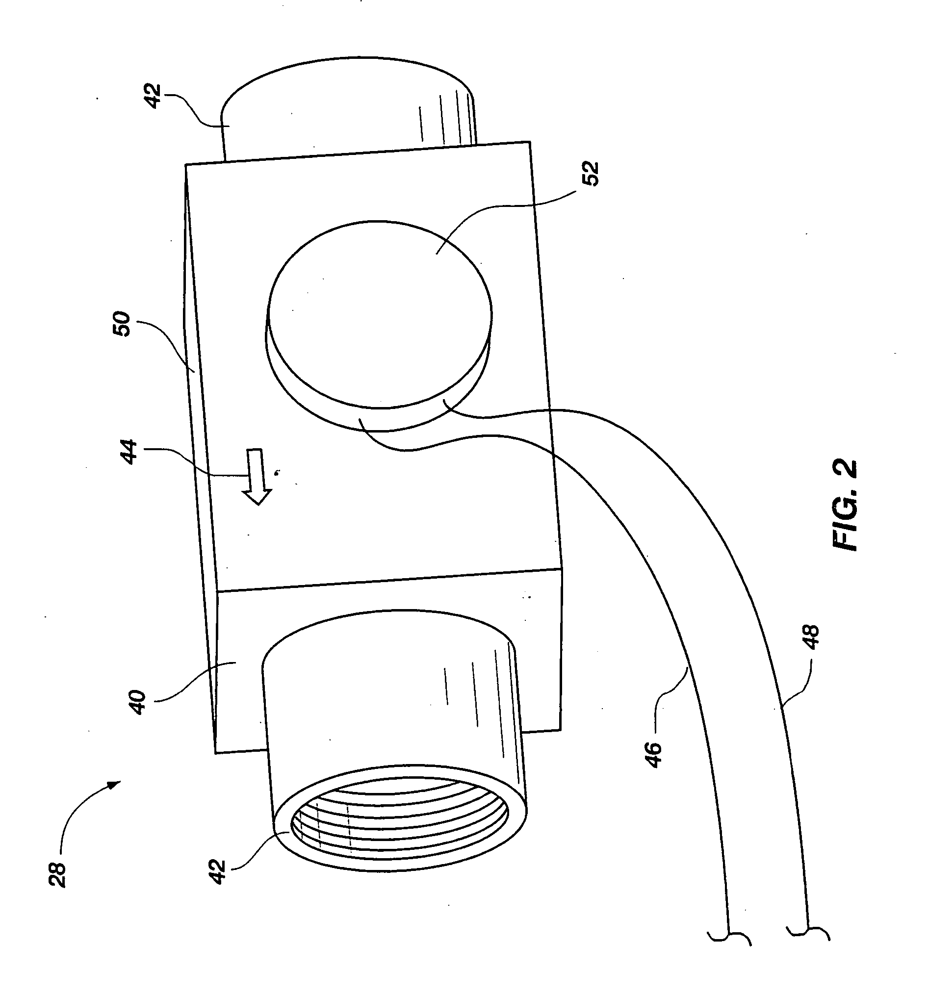
A flow meter that is easily and inexpensively installed in the casing of a well. The flow meter is able to improve the monitoring of private well water usage. The flow meter is typically disposed above an in-the-well pump and below an adapter that directs water outside of the well casing. The flow meter may be connected to a transmitter and antenna for broadcasting flow information to regulatory agencies using communication signals, such as radio frequency, infrared, or other communicating technology. The flow meter should optimally be located below the frost line inside of the casing in locations with cold temperatures. Power to operate the flow meter may be derived from a variety of sources, including a dedicated power line connected to a power source, such as a battery, power grid, or solar power. In addition, the flow meter may generate its own power from the flow of water through the meter.

Description

CROSS-REFERENCE TO RELATED APPLICATIONS [0001] This application claims the benefit of U.S. Provisional Application No. 60 / 854,855, filed Oct. 27, 2006, which is hereby incorporated by reference herein in its entirety, including but not limited to those portions that specifically appear hereinafter, the incorporation by reference being made with the following exception: In the event that any portion of the above-referenced provisional application is inconsistent with this application, this application supercedes said above-referenced provisional application.STATEMENT REGARDING FEDERALLY SPONSORED RESEARCH OR DEVELOPMENT [0002] Not Applicable. BACKGROUND [0003] 1. The Field of the Invention. [0004] The present disclosure relates generally to flow meters, and more particularly, but not necessarily entirely, to flow meters suitable for use with water wells. [0005] 2. Description of Related Art [0006] A water well is an artificial excavation or structure put down by any method such as di...

Claims


Application Information

Patent Timeline
IPC IPC(8): G01F1/34
CPCG01F15/063
Inventor HUNTSMAN, A. RUSSELLHUNTSMAN, SHIRLEY
Owner HUNTSMAN A RUSSELL
Why Eureka
Eureka Blog
Learn More