
Pedal system and method

Active Publication Date: 2008-05-01
ROLAND CORP
View PDF1 Cites 19 Cited by
  • Summary
  • Abstract
  • Description
  • Claims
  • Application Information

AI Technical Summary

Benefits of technology

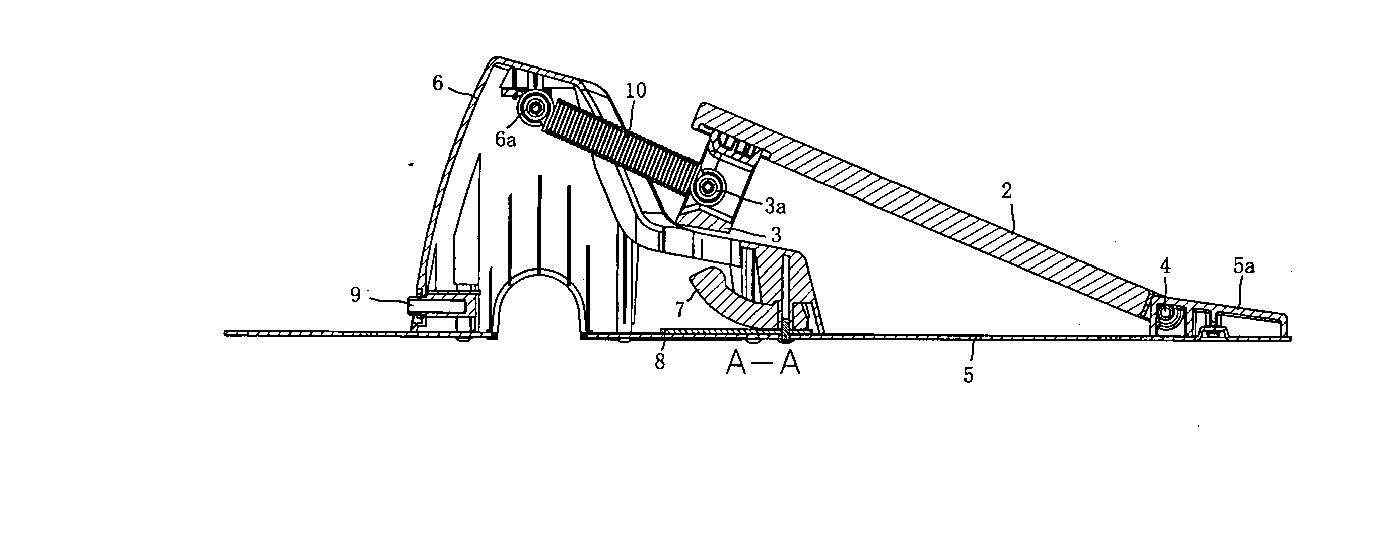
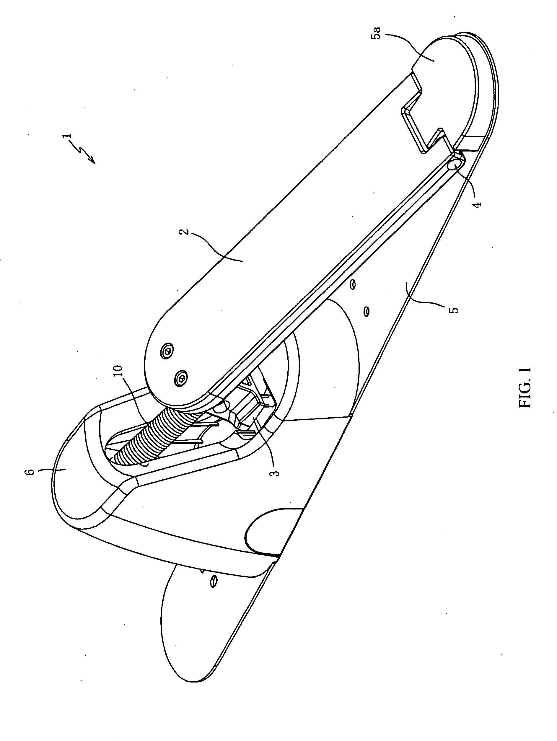
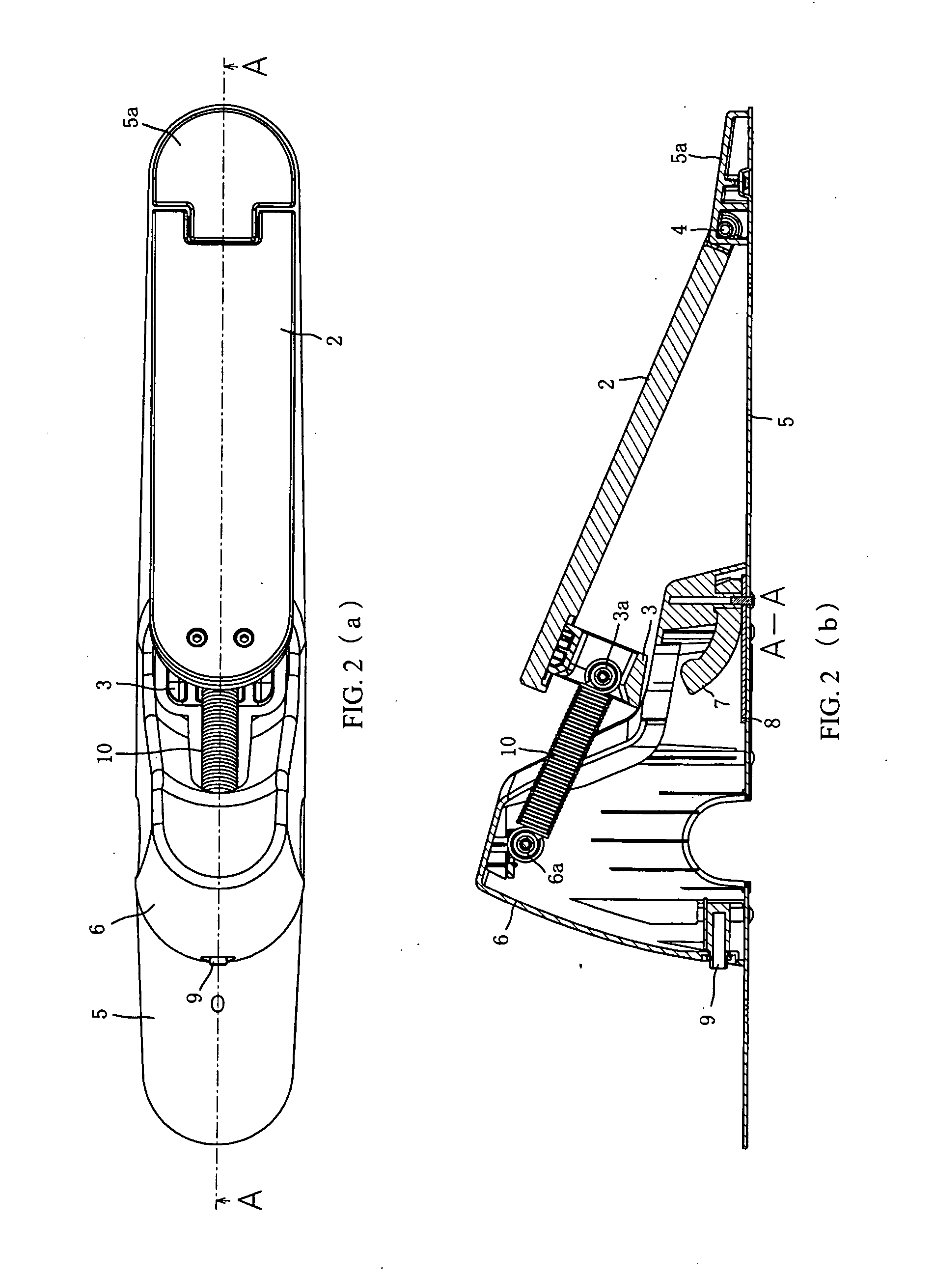
[0008] Embodiments of an electronic percussion instrument pedal device are disclosed. Such embodiments utilize a spring structure in a space between a bottom surface structure and a foot pedal board structure to detect, via a sensor, the movement of the foot pedal board structure relative to the bottom surface structure. When the foot pedal board structure is not pressed, its position is regulated by the above mentioned spring structure along a line from the rotating shaft to a spring stop shaft. In this way, the ability to adjust the foot pedal board structure relative to the bottom surface structure is accomplished via the adjustment of the spring structure. This spring structure can also adjust the angle of the foot pedal board structure relative to the above mentioned bottom surface structure. The spring structure can also be adjusted to enhance the strength of the striking power of the above mentioned foot pedal board structure.
[0010] In another embodiment, insulated electrodes are provided to communicate data from the sensors as output. These electrodes may be attached to the foot board structure via an insulated shock resistant connection structure which allows the connection between the sensor and the foot board structure to be maintained despite undesired movements.

Problems solved by technology

One of the limitation of the device of the first Japanese patent document number described above, is that it required the beater head to physically strike the drum head and thus causing the generation of some unwanted secondary sounds.

Method used


Image

  • Pedal system and method
  • Pedal system and method
  • Pedal system and method

Examples


first embodiment

[0025] A food pedal device according to the present invention includes a foot board structure, where the up and down motion, as well as the limits set upon the motion of the foot board structure is regulated via a spring structure. There are also sensors connected to the foot board structure which sense movements in the structure. The spring structure also maintains the foot board structure at a position level that provides easy strike access to the user when it is not in use. The spring structure can also be utilized to regulate the angle of the resting position for the foot board structure. This set up also allows the foot board structure to utilize the return spring energy to increase the power of the strikes when the foot board structure is stepped upon. As a result, an artist user may find the pedal device to be relatively easy and comfortable to adapt to and use.

[0026] This system can provide ease and comfort of use by being very close to the feel of using a real acoustic bass...

second embodiment

[0034] According to the present invention, the spring is attached to the foot pedal board as well as to the bottom surface structure, and regulates the up and down as well as the resting movement of the foot pedal board along with a first securing structure. A second securing structure is connected to the second end of the spring structure. Thus by utilizing these two securing structure components in conjunction with the spring structure, the electronic percussion instrument pedal device does not need an arm connected to the foot pedal board as in other devices of a similar nature. The pedal thus can be easier to use and more comfortable for the user. Another result is that it becomes much less likely that there will be missed strikes.

[0035] According to a third embodiment of the present invention and also expanding upon the first and second embodiments of an electronic percussion instrument pedal device, sensors are composed of two insulated electrodes formed on bottom plates and a...

third embodiment

[0069] An electronic percussion instrument foot pedal device according to the present invention is described with referenced to FIGS. 7(a) and 7(b). FIG. 7(a) shows a top down view of an electronic percussion instrument foot pedal device 1. FIG. 7(b) shows a side, cross-section view taken along the line A to A in FIG. 7(a).

[0070] In the first embodiment, the foot board 2 was attached to the weight 3 by a series of screws. In the third embodiment, a connective groove 2a extends along the length of the foot board 2. A weight 31 is connected to the connective groove 2a by at least one screw 32, thus adding flexibility, stability and much improved strength to the foot board 2. The screw 32 may be screwed in from the bottom of the foot pedal 2 in such a way as to insure that while they will firmly help attach the weight to the foot pedal and that they will not protrude from the top of the foot pedal 2. The weight 31, like weight 3, may be made of either iron or another dense heavy metal ...


PUM


Abstract

An electronic percussion instrument pedal device uses a spring structure in a space between a bottom structure and a foot pedal board structure to regulate the movement of the foot pedal board structure. Even when the foot pedal board structure is not being moved, it is regulated by the above mentioned spring structure into a proper near horizontal position. If the foot board is stepped on, the coil spring will stretch and a load (stability) will become strong. As a result, when the foot board is in a position near the position in which it is not stepped on, the load is initially relatively light and then becomes heavier as the user continues to further step on the foot board. This is approximated to the action of an acoustic bass drum, and a good actuation feeling.

Description

CROSS-REFERENCE TO RELATED PATENT APPLICATIONS [0001] Japan priority application number 2006-328958, filed on Dec. 6, 2006 is incorporated herein by reference in its entirety. BACKGROUND OF THE INVENTION [0002] This invention relates to pedal device configurations for electronic percussion instrument pedals, and methods of making and using the same. [0003] There are various kinds of electronic percussion instruments. Among them are some that have pedal devices with acoustic bass drums and some in which only a bass drum pedal device is used. The basic structure of the electronic percussion instrument pedal device for an acoustic bass drum has been similar to an electronic percussion instrument pedal device structure. In both structures, the drum head is struck by the downward pressure applied to a foot pedal which is connected to a lever system that moves a beater to strike the drum head to function and produce sounds. Depending upon the power, pressure and duration of the strike, di...

Claims


Application Information

Patent Timeline
IPC IPC(8): G10D13/02
CPCG10H1/348G10H2230/275G10H2220/561
Inventor KITAGAWA, MASAHIRO
Owner ROLAND CORP
Learn More