Gas sensor

Inactive Publication Date: 2004-11-09
DENSO CORP
View PDF7 Cites 7 Cited by
  • Summary
  • Abstract
  • Description
  • Claims
  • Application Information

AI Technical Summary

Benefits of technology

As described above, the present invention can provide a gas sensor capable of preventing cracks and breakage of the gas sensing element.
Furthermore, as the insulator constitutes the main body and the separate body attached via the spacer to the distal end of the main

Problems solved by technology

Thus, the has sensing element is often subjected to a concentrated stress and broken or damaged.
However, as this sealing material is a hard substance, it has difficulty in preventing the gas

Method used


Image

  • Gas sensor
  • Gas sensor
  • Gas sensor

Examples


Example

First Embodiment

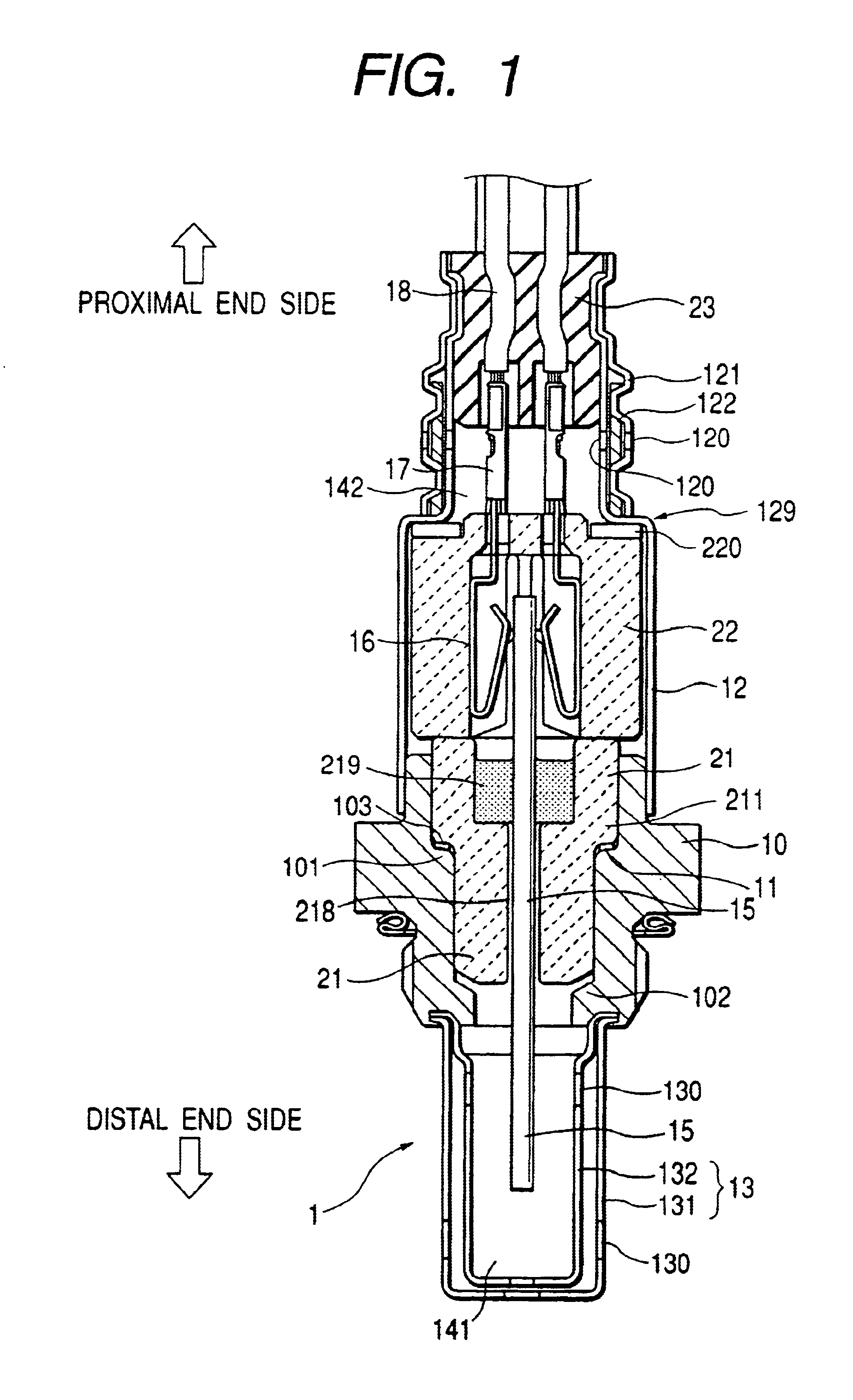
Hereinafter, a gas sensor according to a first embodiment of the present invention will be explained with reference to FIGS. 1 to 7.

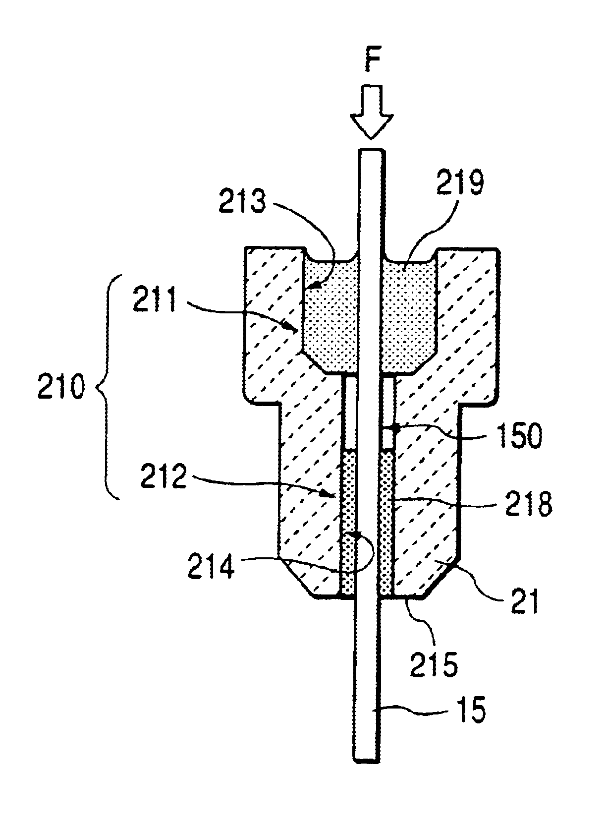
As shown in FIGS. 1 and 2, a gas sensor 1 of this embodiment comprises a insulator 21 having an element insertion hole 210 extending from a proximal end to a distal end thereof, a gas sensing element 15 airtightly fixed in the element insertion hole 210 of the insulator 21, and a cylindrical housing 10 having an inside space for placing the insulator 21, with an air side cover 12 attached to a proximal end of the housing 10 so as to confine an aerial atmosphere 142 therein and a measured gas side cover 13 attached to a distal end of the housing 10 so as to confine a measured gas atmosphere 141 therein.

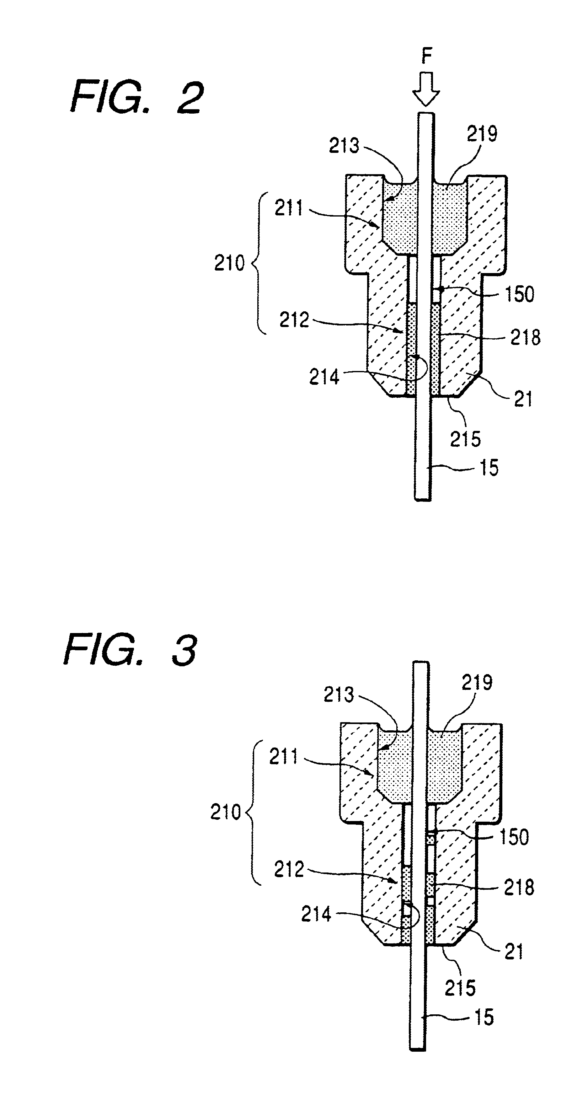
As shown in FIG. 2, the element insertion hole 210 consists of a larger-diameter portion 211 formed at the proximal end thereof and a smaller-diameter portion 212 formed at the distal end thereof. The larger-diameter portion 211 has an inne...

Example

Second Embodiment

As shown in FIG. 9, a second embodiment is characterized in that the insulator 21 consists of a main body 28 and a separate body 29. The element insertion hole 210 extends across both of the main body 28 and the separate body 29. The separate body 29 is attached to a distal end of the main body 28 via a spacer 290. The smaller-diameter portion 212 of the element insertion hole extends from the main body 28 to the separate body 29.

The cushion filler 218 is provided only in the smaller-diameter portion 212 of the separate body 29.

The rest of the arrangement is similar to that of the first embodiment.

The gas sensor in accordance with the second embodiment has the insulator 21 comprising the separate body 29 attached to the main body 28 via the spacer 290. Thus, the shock applied from the outside can be absorbed by the spacer 290. Thus, the strength against the external shock can be further increased.

Furthermore, as the cushion filler 218 is provided only in the separat...

Example

Third Embodiment

As shown in FIG. 10, a third embodiment is characterized in that the element insertion hole 210 consists of a larger-diameter portion 211 formed at the distal end thereof and a smaller-diameter portion 212 formed at the distal end thereof. The larger-diameter portion 211 has an inner diameter larger than that of the smaller-diameter portion 212. The clearance between the inner surface of the larger-diameter portion 211 and the gas sensing element 15 is filled with the cushion filler 218. The clearance between the inner surface of the smaller-diameter portion 212 and the gas sensing element 15 is filled with the sealing material 219.

The rest of arrangement is similar to that of the first embodiment.

This embodiment provides a gas sensor which is strong against external shock. Details of the remaining arrangement is similar to those disclosed in the first embodiment.


PUM


Abstract

A gas sensing element is placed in an element insertion hole of an insulator. The element insertion hole consists of a larger-diameter portion and a smaller-diameter portion. A clearance between an inner surface of the larger-diameter portion and an outer surface of the gas sensing element is filled with a sealing material. A clearance between an inner surface of the smaller-diameter portion and the outer surface of the gas sensing element is filled with a cushion filler having the capability of withstanding a loading force ranging from 5N to 1,000N.

Description

BACKGROUND OF THE INVENTIONThe present invention relates to a gas sensor utilized for an air-fuel ratio control of an internal combustion engine.A gas sensor is installed in an exhaust system of an automotive engine for air-fuel ratio control or the like.A conventional gas sensor comprises a cylindrical insulator having an element insertion hole, a gas sensing element airtightly fixed in the element insertion hole, and a cylindrical housing having an inside space for placing the insulator. An air side cover is attached to a proximal end of the housing so as to confine an aerial atmosphere therein. And, a measured gas side cover is attached to a distal end of the housing so as to confine a measured gas atmosphere therein.As shown in FIG. 13, to facilitate insertion of the gas sensing element 15, the element insertion hole 210 consists of a larger-diameter portion 211 formed at the proximal end thereof and a smaller-diameter portion 212 formed at the distal end thereof. The larger-dia...

Claims


Application Information

Patent Timeline
IPC IPC(8): G01N27/407G01N27/409F02D35/00F02D45/00G01N27/416
CPCG01N27/4077
Inventor KIMATA, TAKEHITOOZAWA, MASATO
Owner DENSO CORP
Why Eureka
Try Eureka