Self-adjusting gambrel

Active Publication Date: 2005-12-13
TEINERT BILL
View PDF23 Cites 7 Cited by
  • Summary
  • Abstract
  • Description
  • Claims
  • Application Information

AI Technical Summary

Benefits of technology

[0008]The present invention also provides for, at most, two pivot points which enhances the overall strength of the apparatus.
[0009]The present invention further provides for a weight-bearing lower cross member which operates to distribute the wei

Problems solved by technology

Conventional gambrels are difficult to use because they are overly complex, difficult to mount, do not easily ad

Method used


Image

  • Self-adjusting gambrel
  • Self-adjusting gambrel
  • Self-adjusting gambrel

Examples


Example

[0015]Referring to the figures in which like referenced features indicate corresponding elements throughout the several views. The references are:

[0016]
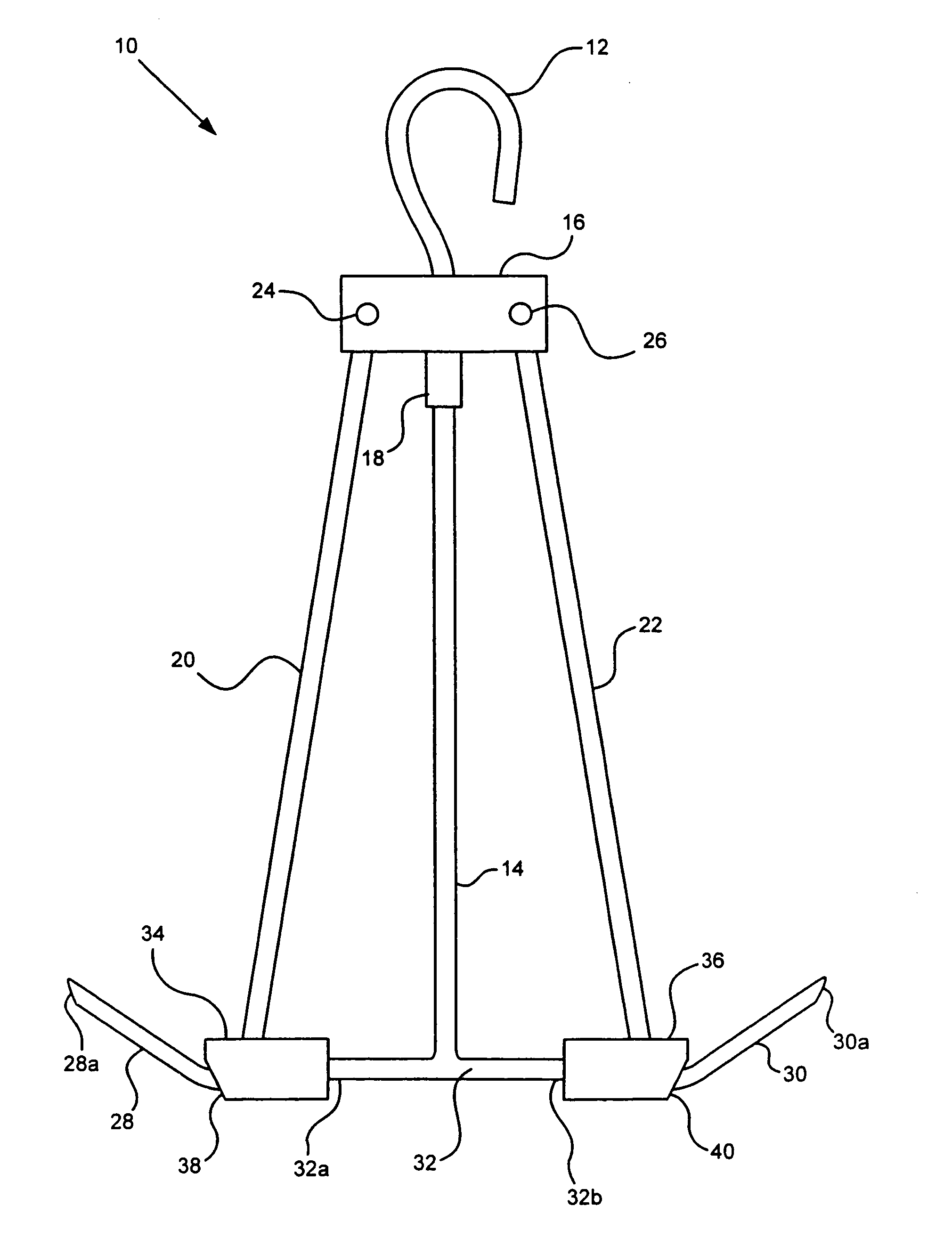
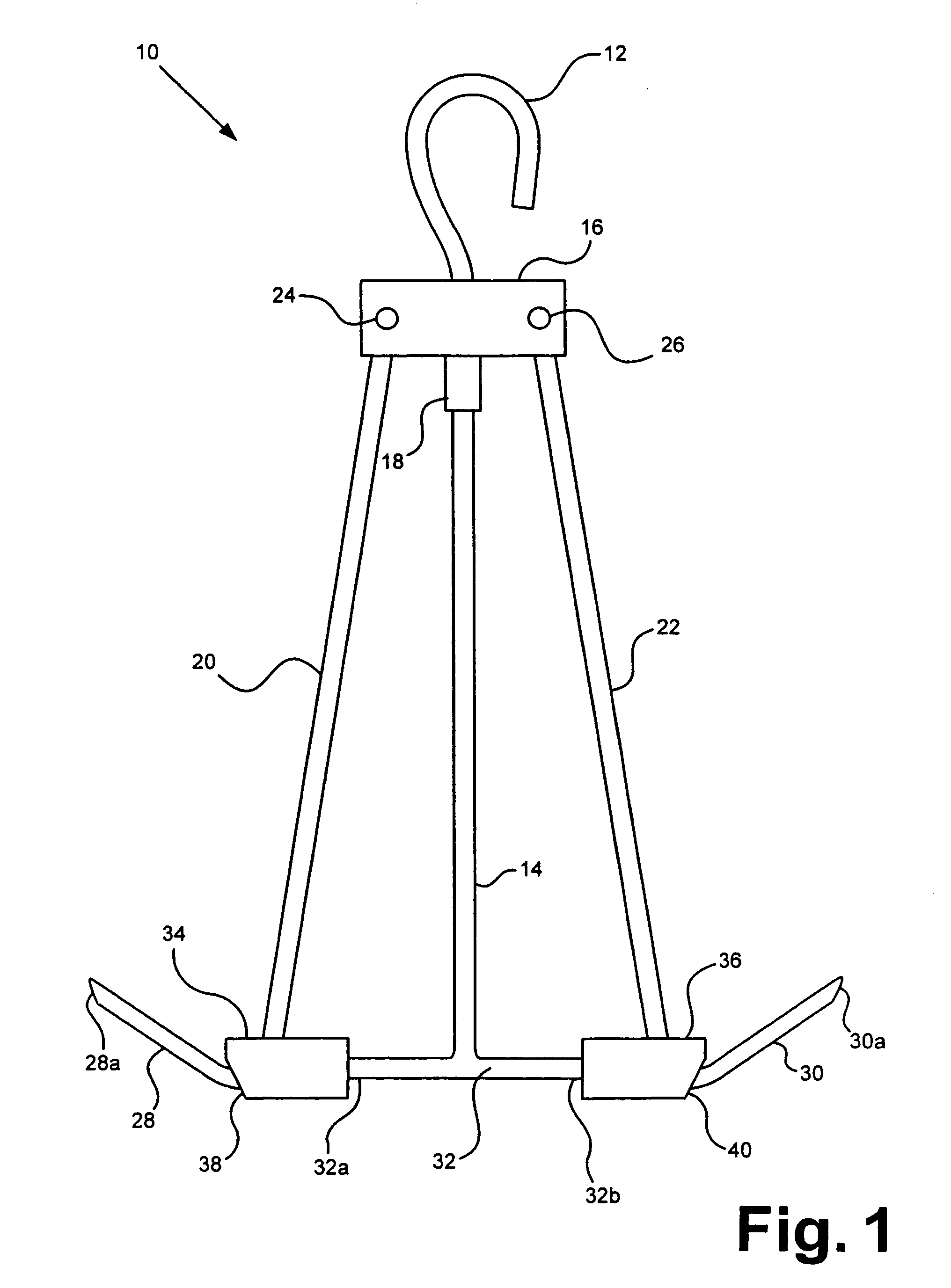
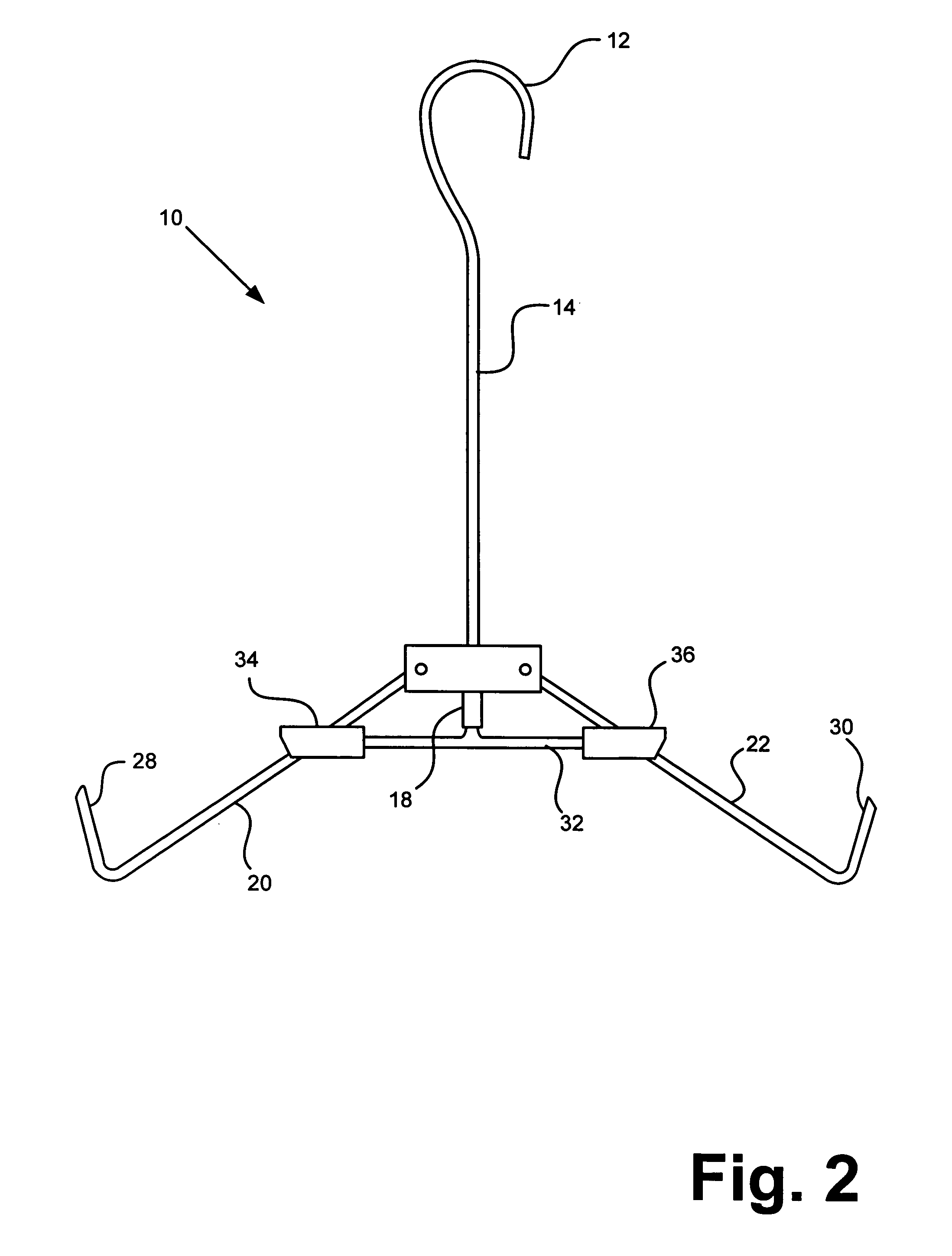
10gambrel12support hook14central bar16upper cross member16aupper cross member first plate16bupper cross member second plate18upper cross member cylinder20first prong arm22second prong arm24first prong arm pivot26second prong arm pivot28first prong28afirst prong tapered end30second prong30asecond prong tapered end32lower cross member32alower cross member first end32blower cross member second end34first lower cross member collar36second lower cross member collar38first notch40second notch

[0017]Attention is first directed to FIG. 1 which illustrates a gambrel (10) in a first, retracted position. The gambrel (10) has a support hook (12) operable to hang the gambrel (10) by a chain, rope, cable, a stationary object, or other supporting means (not shown). The support hook (12) is connected to the first end (no reference number) of the cent...


PUM


Abstract

The present invention consists of an gambrel that can be easily and quickly hung from a variety of mounts to allow for quick, safe, reliable field dressing of slaughtered animals. It will automatically adjust to the size and weight of the slaughtered animal. The gambrel has, at most, two pivot points, which enhances the overall strength of the apparatus. It has a weight-bearing lower cross member which operates to distribute the weight of the slaughtered animal across the entire gambrel and provides for additional strength. The gambrel's hooked mounting mechanism also adds versatility in field dressing the animal.

Description

[0001]This utility patent application takes priority from Provisional patent Application No. 60 / 461,508 filed Apr. 9, 2003, for “A Self-Adjusting Apparatus for Hanging a Carcass.”BACKGROUND OF THE INVENTION[0002]1. Field of the Invention[0003]Applicant's invention relates to a device for hanging a carcass, allowing a hunter to field dress the animal. More particularly, it relates to a portable gambrel which automatically adjusts to the proper size for the animal being dressed.[0004]2. Background Information[0005]Hunters often desire to field dress an animal they have slaughtered. Field dressing an animal reduces the weight that a hunter must carry making it easier to manipulate and handle. Field dressing also helps prevent contamination. Field dressing is most easily accomplished by suspending the animal by its hind legs via a gambrel. Conventional gambrels are difficult to use because they are overly complex, difficult to mount, do not easily adjust for varying sizes and weights of...

Claims


Application Information

Patent Timeline
IPC IPC(8): A22B1/00A22B5/06
CPCA22B5/06
Inventor TEINERT, BILL
Owner TEINERT BILL
Why Eureka
Try Eureka