
Handlebar

Inactive Publication Date: 2014-06-26
TIEN HSIN INDS
View PDF6 Cites 7 Cited by
  • Summary
  • Abstract
  • Description
  • Claims
  • Application Information

AI Technical Summary

Benefits of technology

The invention aims to create a handlebar that is lighter and stronger without a stem.

Problems solved by technology

However, since the circumstance for the race is so tough, during the race, the conventional handlebar set for a bicycle is breakable easily from a connection between the handle portion and the stem portion.
As a result, the conventional handlebar set for a bicycle is not applicable for joining the downhill races.

Method used


Image

  • Handlebar
  • Handlebar
  • Handlebar

Examples


Embodiment Construction

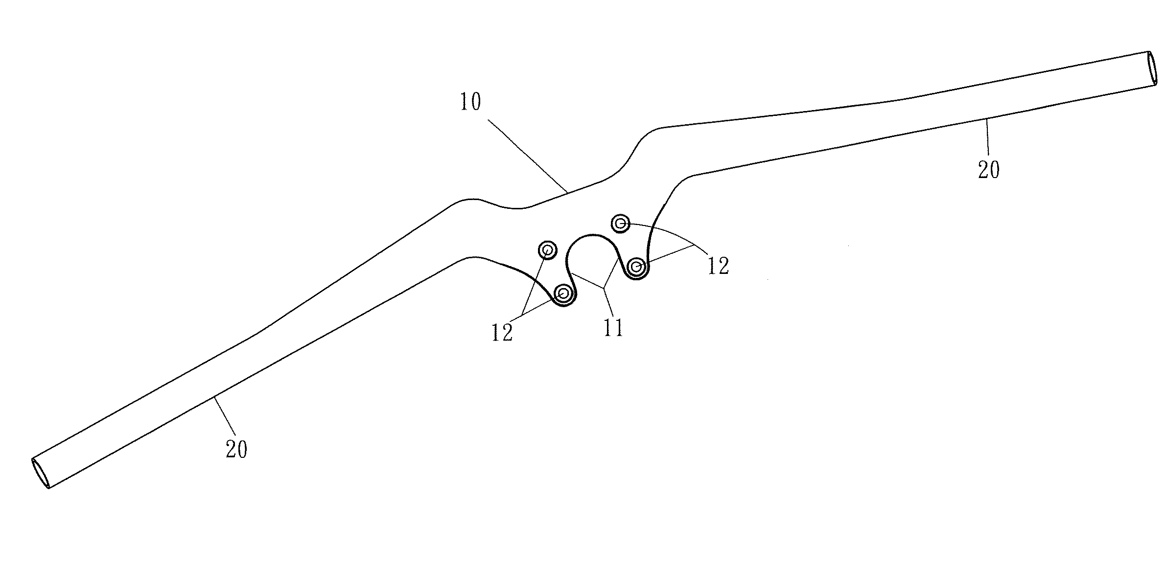
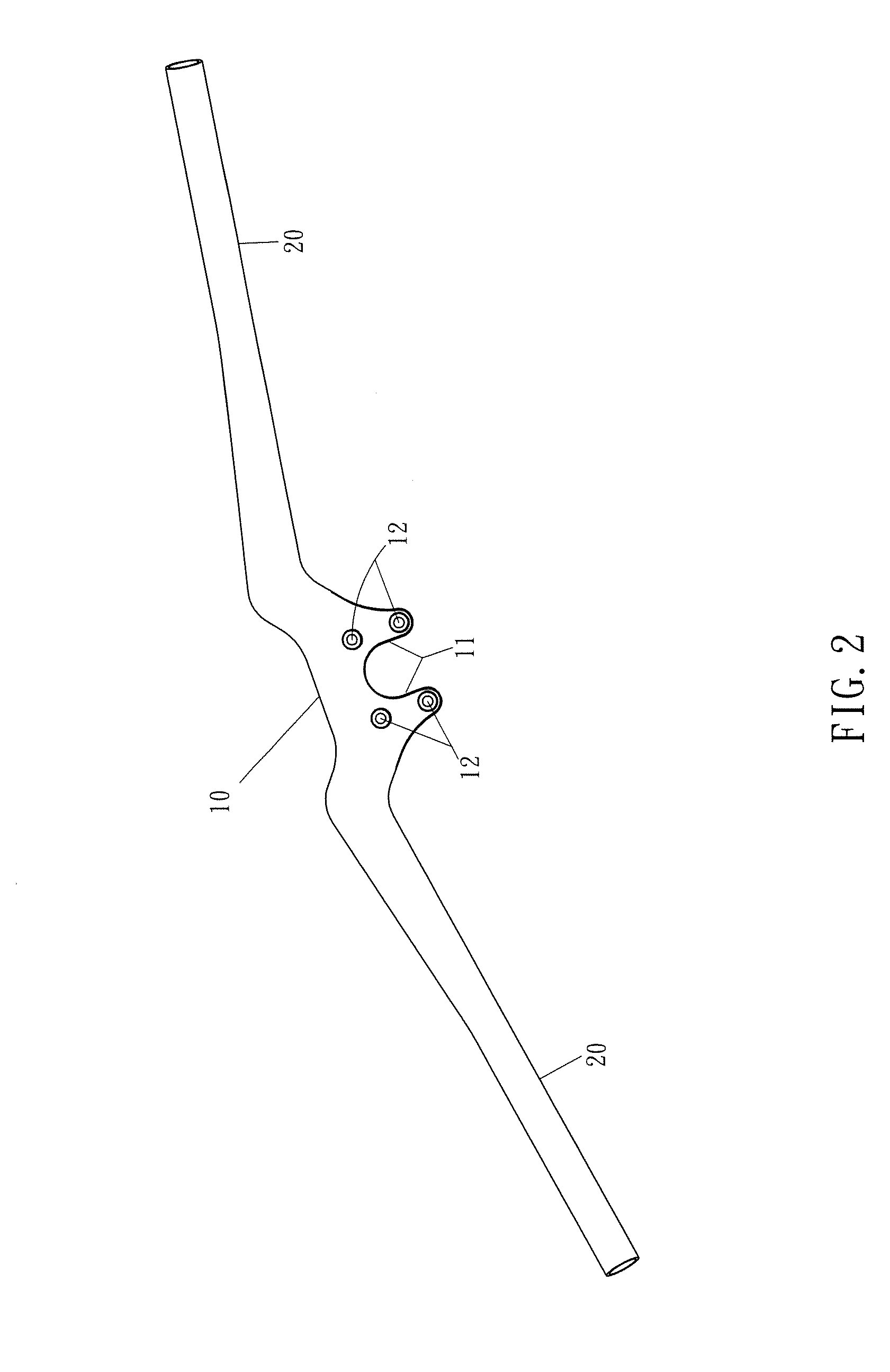
[0018]Referring to FIGS. 2-5, a handlebar of a first embodiment of the present invention is connected to a front fork (not numbered) via four fasteners 30. As shown in FIG. 2, the handlebar includes a main body 10 and two grip portions 20. The main body 10 has an extending portion 11 extended therefrom, as shown in FIG. 2, the main body 10 has two extending portions 11 extended therefrom. Four through holes 12 are opened on the two extending portions 11. The two grip portions 20 are formed at two opposite ends of the main body 10, that is, the two grip portions 20 and the main body 10 are formed integrally as a whole. The two grip portions 20 are formed adjacent to the surface where the extending portions 11 extended from. As shown in FIG. 5, each fastener 30 passes each corresponding through hole 12 to be secured on the front fork, so that the main body 10 is fastened on the front fork.

[0019]Referring to FIG. 4, the handlebar further has an inclined surface 14 descended from the ma...


PUM


Abstract

A handlebar includes a main body and two grip portions. The main body includes at least one extending portion extended away from the main body, and at least one through hole opened on the extending portion. The two grip portions are formed at opposite ends of the main body. The advantage of the handlebar is to omit the stem that can lighten the weight and reduce the wind resistance to make the riders safer and comfortable riding.

Description

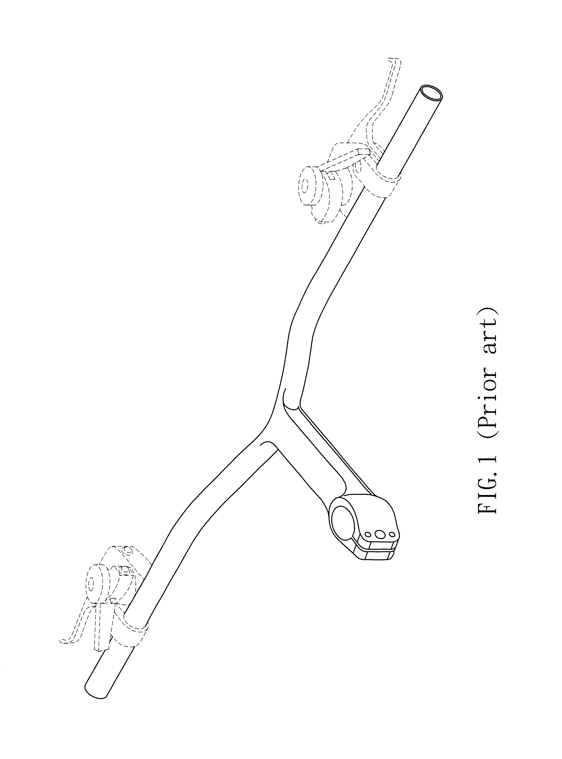
BACKGROUND OF THE INVENTION[0001]1. Field of the Invention[0002]The present invention relates to a handlebar, and more particularly, to a handlebar which is directly assembled to a front fork of a bicycle without the application of a stem.[0003]2. Description of Related Art[0004]Bicycle downhill race is a popular activity for many cyclers. Racers ride on the mountain road or wild road which is unsmooth and bumpy so as to compete with each other.[0005]Referring to FIG. 1, a conventional handlebar set for a bicycle is made of carbon fiber. The conventional handlebar set for a bicycle includes a handle portion. A middle part of the handle portion has a stem portion extended therefrom. One end of the stem portion has a stem hole opened thereon so as to assemble with a fork portion of a bicycle. The handle portion has two grip portions extended therefrom for the rider to grip on. Under this arrangement, the weight of the conventional handlebar set for a bicycle is greatly reduced and sti...

Claims


Application Information

Patent Timeline
IPC IPC(8): B62K21/12
CPCB62K21/12Y10T74/2078
Inventor CHIANG, YOU-RONG
Owner TIEN HSIN INDS
Learn More