Device for Dispensing a Fluid from the Hollow Space of a Container

a technology for liquid dispensing and hollow spaces, which is applied in the direction of liquid dispensing, packaging, dispensing apparatus, etc., can solve the problems of corresponding drop in the pressure over the liquid, difficulty in maintaining the reference pressure inside the third chamber, and considerable disadvantages of the pressure regulation concept being applied, etc., to achieve the effect of reducing the cost of the device, reducing the cost, and simplifying the structure and assembly of the device according to the invention

Inactive Publication Date: 2008-05-01
SCHNEIDER PETER +3
View PDF6 Cites 5 Cited by
  • Summary
  • Abstract
  • Description
  • Claims
  • Application Information

AI Technical Summary

Benefits of technology

[0014] Another advantage of the invention is that an empty container can be provided with the pressure reservoir and the pressure regulation mechanism at the manufacturer, and that the container can later be filled independently thereof at the filling plant, while the pressure regulation mechanism can be activated at any chosen time. The pressure regulation mechanism can be activated when the container is filled, for example, or not until some time later, for example by the end-user when he or she wishes to start dispensing the contents. Since a enclosed gas reservoir is not required in order to provide a reference pressure, the structure and assembly of the device according to the invention are greatly simplified and less expensive. Regulation is not impaired, even over protracted storage periods, when plastic injection-molded parts are used to manufacture the device at low cost. The pressure regulation mechanism can be mounted together with the pressure reservoir at any position on the container.
[0015] Another advantage of the device according to the invention is that ready-made containers can be fitted with the pressure reservoir and the pressure regulation mechanism by the manufacturer, and filled and / or sealed, without adaptation being necessary, via the center opening in the container lid that is standard in such containers. Conventional filling and sealing plant can therefore be used, such as that commonly used in the beverage industry for party cans, for example, without modifications having to be made to such plant.
[0016] In one advantageous development of the invention, the pressure reservoir is configured as a pressure cartridge with an integrated discharge valve.
[0017] This enables conventional pressure cartridge to be used, thus achieving simple construction and cost-efficient production.
[0018] It is appropriate here to use the kind of pressure cartridges in which the gaseous propellant is combined with a filler additive, such as activated carbon. In this way, a much lower filling pressure can be used in the pressure cartridge that would be possible in the absence of such an absorbent.
[0019] In another advantageous embodiment of the invention, the pressure reservoir includes a discharge valve that is biased in the direction of the closed position with a force less than the force exerted by the biasing means.

Problems solved by technology

Although such a pressure regulation mechanism is basically suitable for generating an approximately constant pressure inside a container, such as inside a spray can, the pressure regulation concept being applied involves considerable disadvantages.
However, maintaining the reference pressure inside the third chamber is difficult over a longer period.
Especially when manufacturing tolerances are taken into consideration, a certain loss of pressure from the reference chamber can be expected for storage periods lasting several months, which naturally leads to a corresponding drop in the pressure over the liquid as adjusted by the pressure regulator.
Even when using high-quality precision-made parts with small tolerances, losses due to diffusion and migration can be expected in the course of time because it is difficult to achieve a perfect seal of a gas volume over a longer period of time.
There is therefore a risk, especially after a long period in storage, that the reference pressure will drop over time, with the result that the pressure regulator is no longer able to set the desired pressure over the liquid.

Method used


Image

  • Device for Dispensing a Fluid from the Hollow Space of a Container
  • Device for Dispensing a Fluid from the Hollow Space of a Container
  • Device for Dispensing a Fluid from the Hollow Space of a Container

Examples


Embodiment Construction

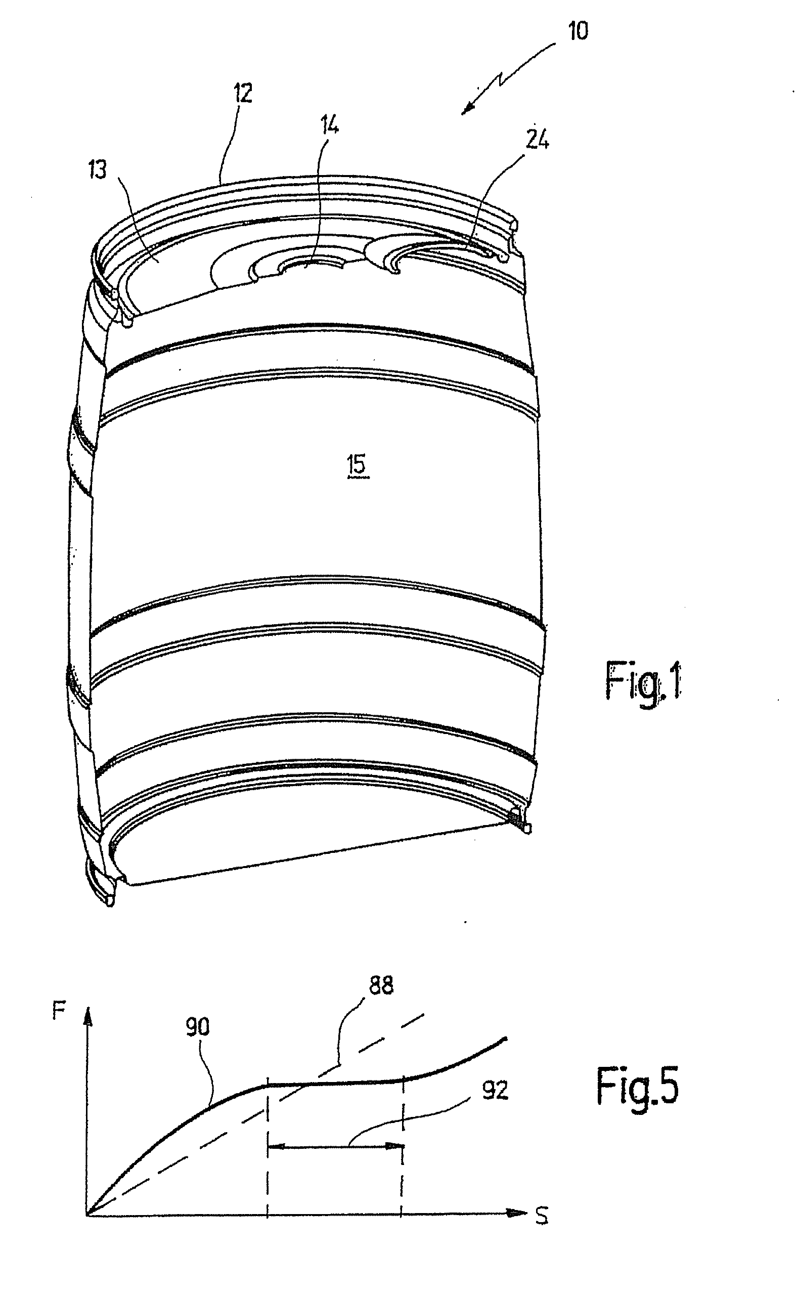
[0073] A device according to the invention is shown in FIG. 1, where it is labeled in its entirety with reference numeral 10. Device 10 is a beverage container for receiving a beverage under gas pressure, such as beer. Such containers are available as party kegs with volumes of three, five or ten liters and are provided on their lid surface 13 with a central opening 14 in which a plug is received and which is configured for filling the container and emptying it with a suitable dispensing device, such as the one known from DE 298 22 430 U1.

[0074] Although it is not shown in FIG. 1, such a container 10 can also be provided with a dispensing valve integrated in the side wall of the container that can be pulled out when required in order to withdraw fluid from the container, as known, for example, from U.S. Pat. No. 6,053,475, the entire disclosure of which is incorporated by reference in the present disclosure.

[0075] Such containers are used, in particular, to keep and tap beer. Alth...


PUM


Abstract

Disclosed is a device for dispensing a fluid, in particular a carbonated beverage, from a storage chamber of a container towards the outside via at least one closeable discharge port, comprising a pressure reservoir which is separated from the storage chamber and in which a pressurized propellant is accommodated, and which can be connected to the storage chamber via a pressure regulation mechanism. The pressure regulation mechanism includes an axially moveable regulating element that is impinged upon by means of a spring in the direction of an open position in which propellant is discharged from the pressure reservoir into the storage chamber. The ambient pressure to which the container is exposed acts upon the regulating element in the direction of the open position, and the internal pressure inside the storage chamber of the container acts upon the regulating element in the direction of the closed position.

Description

CROSS REFERENCES TO RELATED APPLICATIONS [0001] This application is a continuation of International Patent Application PCT / EP2005 / 003238, filed on Mar. 26, 2005 designating the U.S., which International Patent Application has been published in German language and claims priority of German patent application 102004017171.8, filed on Apr. 2, 2004 the entire contents of which is incorporated herein by reference.BACKGROUND OF THE INVENTION [0002] The invention relates to a device for dispensing a fluid, in particular a fluid such as beer or the like, from a storage space of a container via at least one closeable dispenser outlet to the outside, comprising a pressure reservoir which is separated from the storage chamber and in which a pressurized propellant is accommodated, and which can be connected to the storage chamber via a pressure regulation mechanism. [0003] Such a device is known from U.S. Pat. No. 5,368,207. [0004] This latter device is a pressurized container, for example a sp...

Claims


Application Information

Patent Timeline
Patent Type & Authority Applications(United States)
IPC IPC(8): B67D1/04B65D83/14
CPCB67D1/0418B65D83/663B65D83/14
Inventor SCHNEIDER, PETERTHEWES, RUDOLPHHAEUSSLER, BERNDKRAUSE, KARL-FRIEDRIDH
Owner SCHNEIDER PETER
Why Eureka
Try Eureka