
Adjustable and progressive coil spring system for two wheeled vehicles

a two-wheeled vehicle and coil spring technology, applied in the direction of shock absorbers, steering devices, cycle equipments, etc., can solve the problems of static system, inability of rider to adjust spring compression characteristics or spring preload while riding, and disclose the function of the device, so as to improve handling performance, reduce the number of working parts, and add a significant amount of weight to the system

Inactive Publication Date: 2008-05-01
HAYES BICYCLE GROUP
View PDF18 Cites 120 Cited by
  • Summary
  • Abstract
  • Description
  • Claims
  • Application Information

AI Technical Summary

Benefits of technology

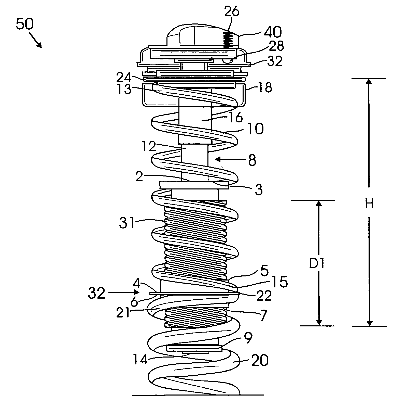
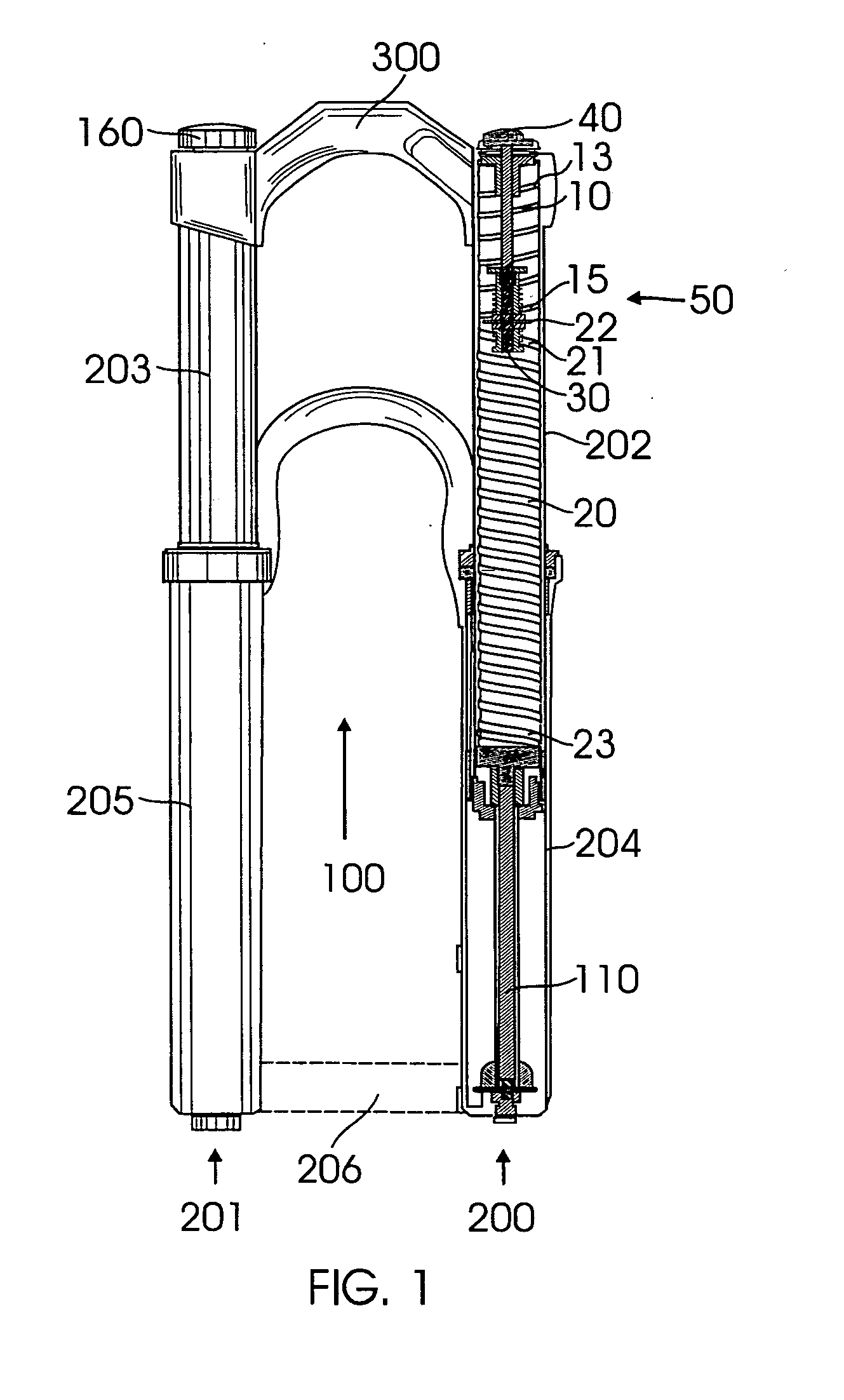
[0036]It has been discovered, according to a first preferred embodiment of the present invention, that if a spring system contained in a bicycle fork leg comprises a first soft spring mounted on top of a second firmer spring, then if the first soft spring is engaged with an adjustment means located at a readily accessibly position on a bicycle fork leg, then the spring compression characteristics of the system can be readily modified by the adjustment means causing the travel length of the first soft spring to be increased or deceased.
[0048]It is still a further object of the present invention to provide a spring system containing a first shorter soft spring in conjunction of a second longer firm spring and an adjustable means for absorbing shock that provides a one coil spring system which satisfies many different riders having varying weights and ride stiffness preferences.

Problems solved by technology

The problem with the prior art is that it's a static system.
Once the rider selects the spring characteristics, the rider cannot adjust the spring compression characteristics or spring pre-load while riding.
The Ueno Design Patent that protects the shape or ornamental beauty of a shock absorber for a motorcycle but does not disclose how the device functions.

Method used


Image

  • Adjustable and progressive coil spring system for two wheeled vehicles
  • Adjustable and progressive coil spring system for two wheeled vehicles
  • Adjustable and progressive coil spring system for two wheeled vehicles

Examples


second embodiment

[0077]Referring to FIG. 7, there is illustrated second preferred embodiment of the vehicle fork 100′ containing the present invention adjustable and progressive coil spring system 50′ placed inside of a first fork leg 200′. In contrast to the configuration where the first soft spring 10 sits on the top of the firm second spring 20 as in the first preferred embodiment shown in FIG. 1, in this second embodiment the second firm spring 20 can be arranged to sit on the top of the first soft spring 10 in conjunction of the coupler assembly 30. As illustrated, the first fork leg 200′ is comprised of the inner telescoping hollow rod 202 movably received within the outer telescoping hollow rod 204, when the first fork leg 200′ at the outer end of the inner telescoping hollow rod 202 is transversely connected to the crown 300, and at the outer end of the outer telescoping hollow rod 204 transversely connected to the wheel axle 206. Within the hollow telescoping rods, there are installed with ...

first embodiment

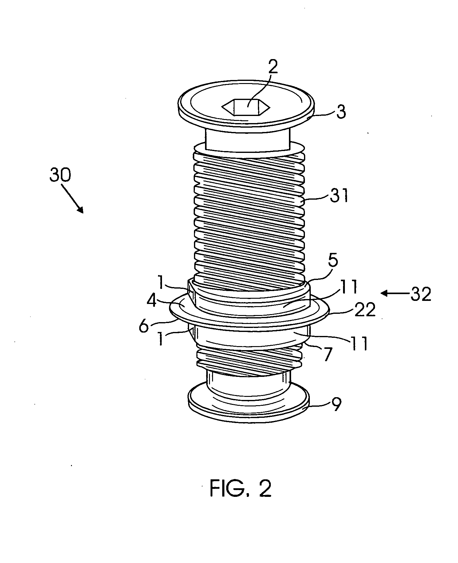
[0081]Defined in detail as a first embodiment, the present invention is a coil spring system to be used within a leg of a bicycle fork comprising: (a) a first soft spring with a first and second end having a given height when in the fully extended condition, and a second firm spring with a first and second end having a greater height than the first soft spring; (b) a coupler assembly comprising a coupler and a threaded bolt, the coupler having a first and second end including an internally threaded bore and a transverse outer ring located at the middle of the coupler, the transverse ring having a first surface and a second surface wherein the first soft spring at its second end rests on the first surface and the second firm springs at its first end rests below the second surface, the first soft spring positioned above the second firm spring so that a the first end of the first soft spring rests adjacent a top end of the vehicle fork leg, the threaded bolt having a first and second e...

third embodiment

[0087]For a third embodiment defined in detail, the present invention is a coil spring system to be used within a leg of a bicycle fork comprising: (a) a first soft spring with a first and second end having a given height when in the fully extended condition, and a second firm spring with a first and second end having a greater height than the first soft spring; (b) a coupler assembly comprising a coupler and a threaded bolt, the coupler having a first and second end including an internally threaded bore and a transverse outer ring located at the middle of the coupler, the transverse ring having a first surface and a second surface wherein the first soft spring at its first end rests below the second surface and the second firm springs at its second end rests on the first surface, the first soft spring positioned below the second firm spring so that a the second end of the first soft spring rests adjacent a bottom end of the vehicle fork leg, the threaded bolt having a first and sec...


PUM


Abstract

An adjustable coil spring system placed within a leg of a vehicle such as a mountain bicycle fork. The spring system comprises an adjustable first soft spring seated on top of a second firm spring having greater length than the first soft spring. A coupler assembly is positioned between two springs comprised of a threaded bolt threadedly received within a coupler. A spring adjustment means may comprise a knob connected to the threaded bolt through a non-round shaped shaft, wherein the threaded bolt is disposed within the first soft spring. As the knob rotates, the coupler is moved up along the threaded bolt, decreasing the length of the first soft spring, thereby increasing firm spring characteristics of the spring system. As the knob rotates in an opposite direction, the coupler moves down, increasing the length of the first soft spring, thereby increasing soft spring characteristics of the spring system.

Description

BACKGROUND OF THE INVENTION[0001]1. Field of the Invention[0002]The present invention relates to the field of spring characteristics in vehicle suspension systems such as those used in bicycle and motorcycle suspension systems that are designed to improve compressibility of a spring system in response to riding conditions and the rider's weight.[0003]2. Description of the Prior Art[0004]Spring and shock distribution systems for changing the spring characteristics of a mountain bicycle fork depending on the riding conditions or the rider's weight are generally known. In the prior art, one way to change the spring characteristics is to change the entire spring assembly to a different spring assembly. In general, the rider wants a suspension spring to be soft in normal travel but if the rider hits bumps, it needs to be stiffer so the rider has a bottom out protection. In the prior art, another variation is to have one spring with two characteristics. Also, another variation is to have ...

Claims


Application Information

Patent Timeline
Patent Type & Authority Applications(United States)
IPC IPC(8): F16F1/06
CPCB62K25/08F16F3/04F16F1/121
Inventor SCHROEDER, BRADY MATTHEW
Owner HAYES BICYCLE GROUP
Learn More