Transport system and method

a technology of transportation system and transportation method, applied in the field of transportation system, can solve the problem that the wheeled structure can be quite heavy to be moved by humans, and achieve the effect of improving the safety and safety of workers

Inactive Publication Date: 2008-05-01
CAPSA SOLUTIONS
View PDF12 Cites 32 Cited by
  • Summary
  • Abstract
  • Description
  • Claims
  • Application Information

AI Technical Summary

Problems solved by technology

Some of the wheeled structures can be quite heavy to be moved by humans, particularly if the wheeled structures are carrying additional weight such as with a hospital bed carrying a patient or a shelving unit holding stored items.

Method used


Image

  • Transport system and method
  • Transport system and method
  • Transport system and method

Examples


Embodiment Construction

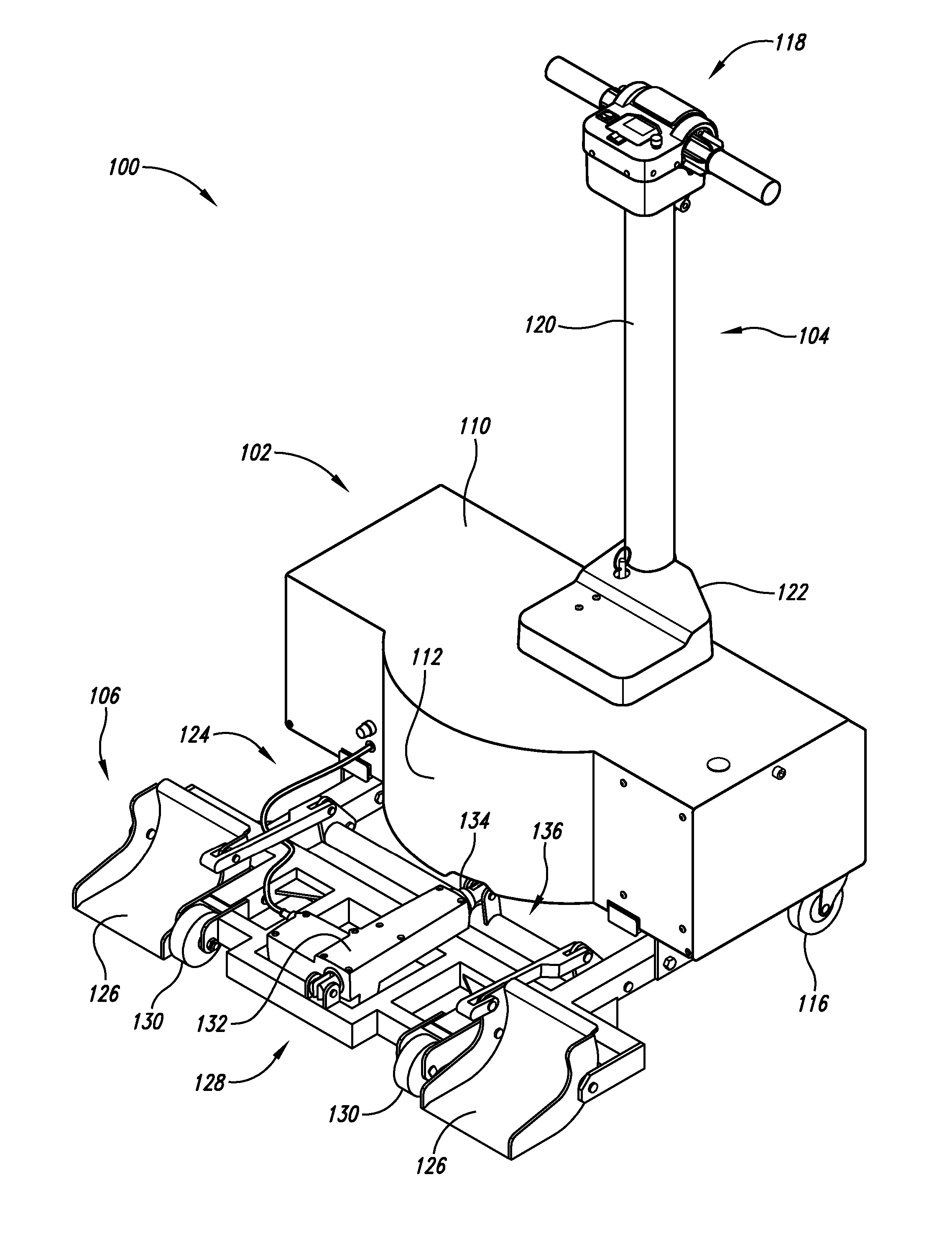
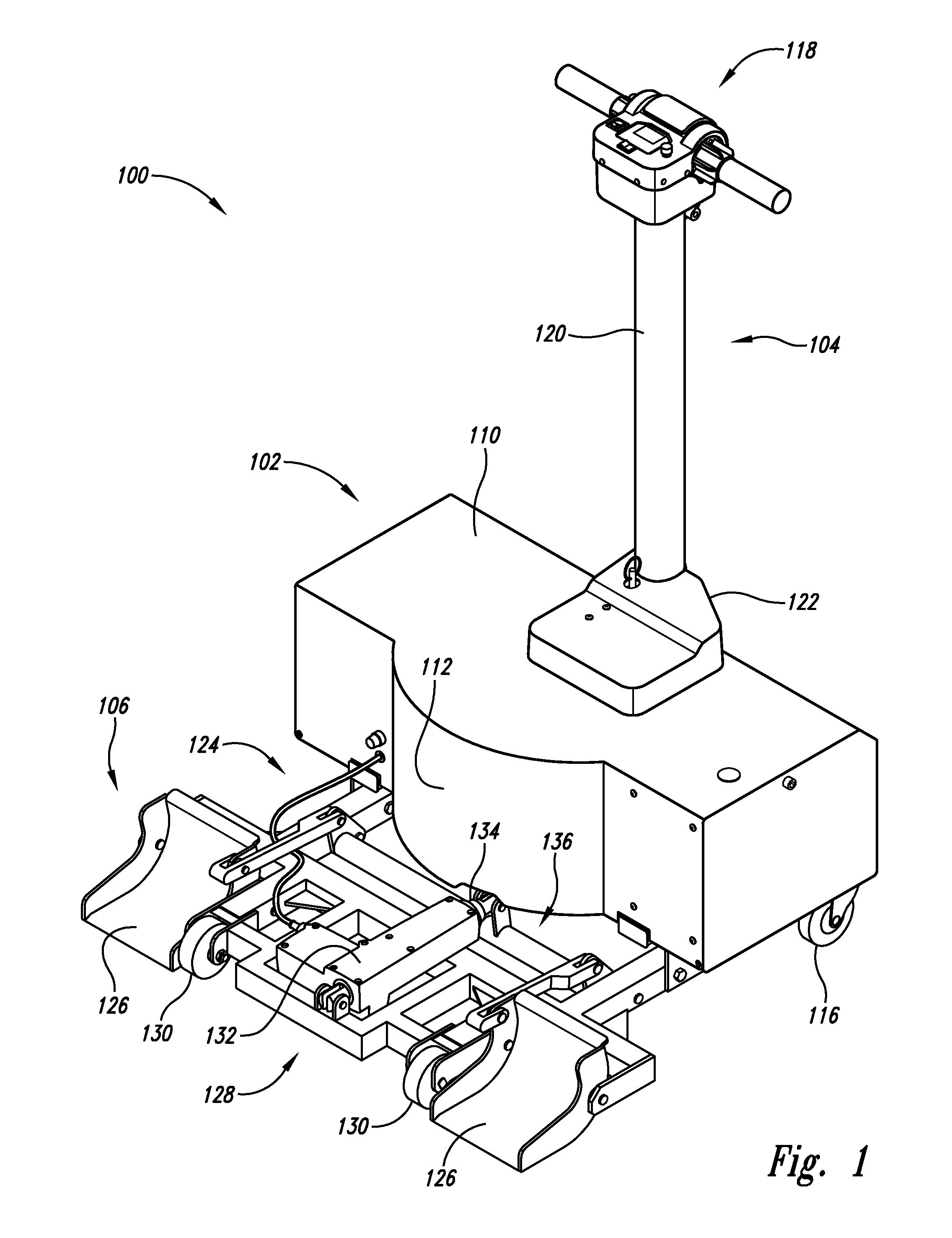
[0027] As will be discussed in greater detail herein, a transport system is used to move wheeled structures, such as beds and shelving units. A wheeled bed is depicted in a first implementation and a shelving unit in an alternative implementation, but other wheeled structures can also be moved by the transport system. The compact design of the first implementation allows the transport system when coupled with a bed to be maneuvered through space restricted areas such as elevators.

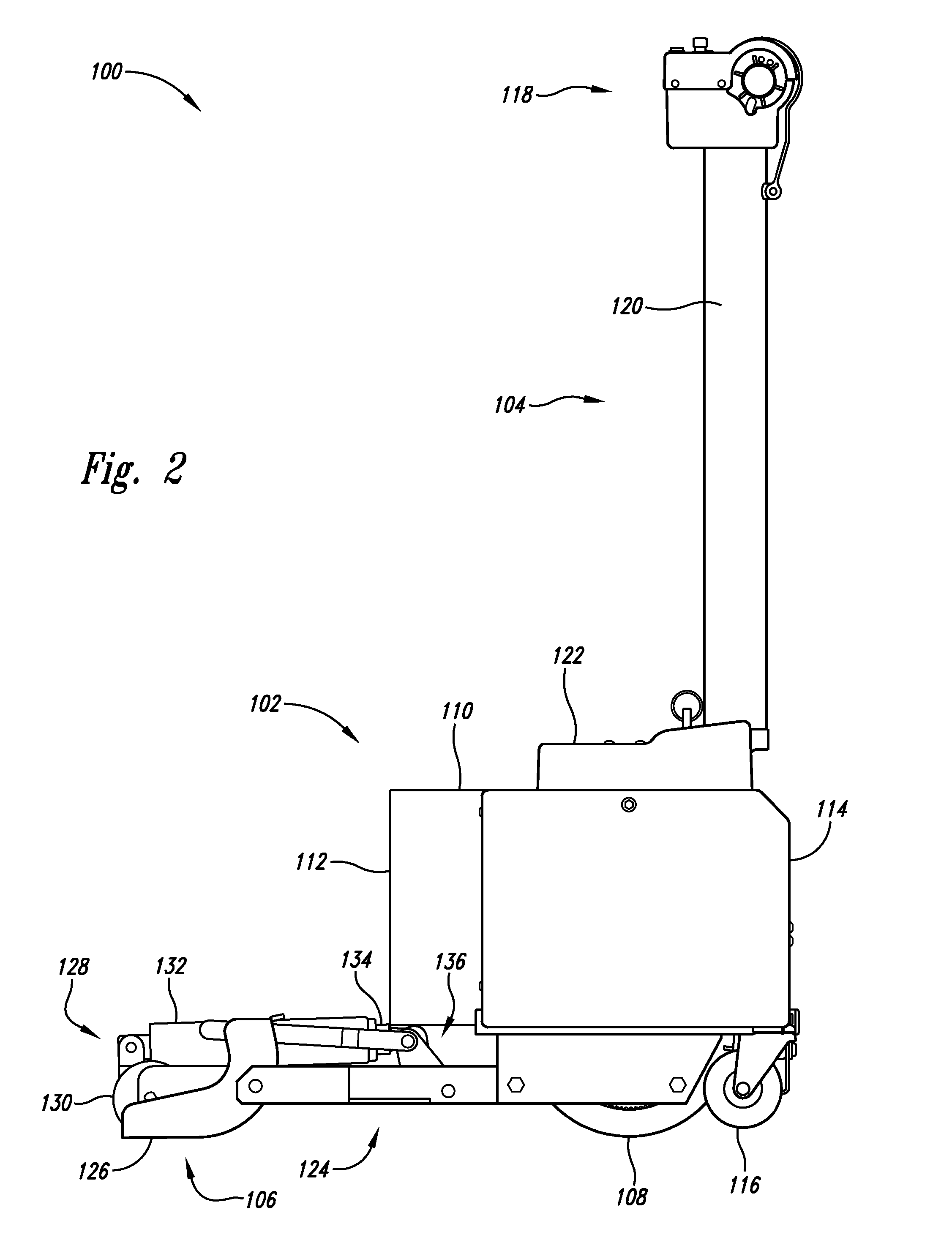
[0028] As shown in FIG. 1, an exemplary first implementation of a transport system 100 includes a drive unit 102, a steering unit 104, and an engagement unit 106. The drive unit 102 includes a source of motive power such as a motor (not shown) and at least one drive wheel 108 (shown in FIG. 2) coupled to the motor to provide motive force to the transport system through frictional engagement with a floor surface. The drive unit 102 further includes a housing 110 with a forward end 112 and an aft end 114 tha...


PUM


Abstract

As will be discussed in greater detail herein, a transport system is used to move wheeled structures, such as beds. A wheeled bed will be used as the depicted implementation, but other wheeled structures can also be moved by the transport system. The compact design of the transport system allows the transport system when coupled with a bed to be maneuvered through space restricted areas such as elevators.

Description

CROSS REFERENCE TO RELATED APPLICATION [0001] This application claims priority benefit of provisional application Ser. No. 60 / 863,537 filed Oct. 30, 2006, the content of which is incorporated in its entirety.BACKGROUND OF THE INVENTION [0002] 1. Field of the Invention [0003] The present invention is directed generally to transport systems for wheeled structures. [0004] 2. Description of the Related Art [0005] Wheeled structures include shelving units and beds, such as hospital type beds. The wheeled structures have wheels coupled to leg bottoms to give a degree of mobility. Some of the wheeled structures can be quite heavy to be moved by humans, particularly if the wheeled structures are carrying additional weight such as with a hospital bed carrying a patient or a shelving unit holding stored items.BRIEF DESCRIPTION OF THE SEVERAL VIEWS OF THE DRAWING(S) [0006]FIG. 1 is a perspective view of a depicted version of a transport system with concave blade members in the down position. [...

Claims


Application Information

Patent Timeline
Patent Type & Authority Applications(United States)
IPC IPC(8): B62B3/06A61G7/08B66F5/00
CPCA61G7/08B62B3/0612B66F5/04B62B2202/90B62B2202/30
Inventor WANER, JOHN A.RUMER, MICHAEL LEEPAU, MAXLAM, KAI-CHI
Owner CAPSA SOLUTIONS
Why Eureka
Try Eureka