
Holder Identifying Apparatus, Component Supplying Method And Mounter

Inactive Publication Date: 2008-05-01
PANASONIC CORP
View PDF9 Cites 6 Cited by
  • Summary
  • Abstract
  • Description
  • Claims
  • Application Information

AI Technical Summary

Benefits of technology

[0010]The present invention is conceived in view of the above problem, and an object of the present invention is to provide a holder identifying apparatus which can perform high control over a component holder that can perform communication compliant only with a general specification without disclosing a communication specification used for the communication with a mounter.
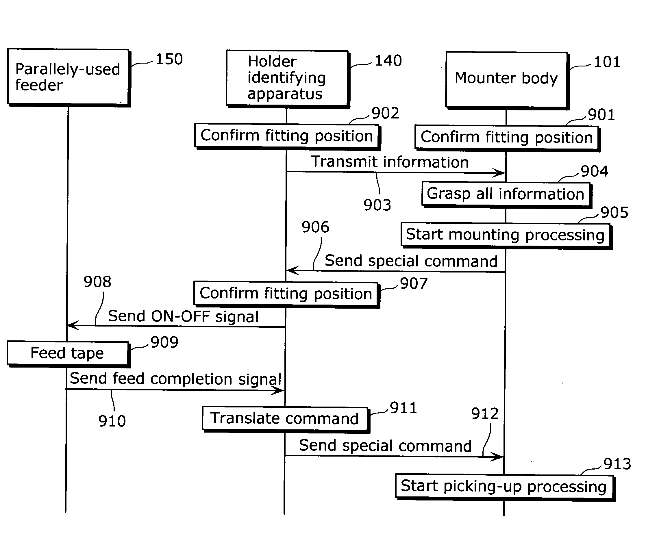
[0012]Thus, the component holder which is used together with the holder identifying apparatus for combined use does not need to directly exchange information with the mounter, and thus does not need to disclose a communication specification to an order destination even in the case of contracting out the component holders. The type of the component holder can be flexibly changed only by rewriting the information stored in the holder information storage unit.
[0014]Thus, the component holder installed in the holder identifying apparatus does not need to directly receive a control command from the mounter and is controlled based on the communication specification predetermined for the communication with the holder identifying apparatus. It is therefore possible to highly control the component holder without disclosing a communication specification to an order destination even in the case of contracting out the component holders.
[0017]Thus, a positional relationship between the holder identifying apparatus and the component holder installed therein can be easily and visually checked in the state where the both are equipped to the mounter. This reduces the operator's burden of checking if the apparatus and the holder are set properly and prevents them from being inappropriately installed.
[0019]Thus, the component holders which supply components of various types or components of the same type can be recognized at once, so that the component holders can be easily controlled with less number of components.
[0021]It is possible to highly control the component holder that can perform communication compliant only with a general specification without disclosing the communication specification used for the communication with the mounter.

Problems solved by technology

Such communication specification is closely related to an operation of a mounter, and therefore, the disclosure of the communication specification may expose the operation procedure and the method of controlling the mounter to the risk of being decrypted.

Method used


Image

  • Holder Identifying Apparatus, Component Supplying Method And Mounter
  • Holder Identifying Apparatus, Component Supplying Method And Mounter
  • Holder Identifying Apparatus, Component Supplying Method And Mounter

Examples


Embodiment Construction

[0040]The following describes the embodiment of the present invention with reference to the diagrams.

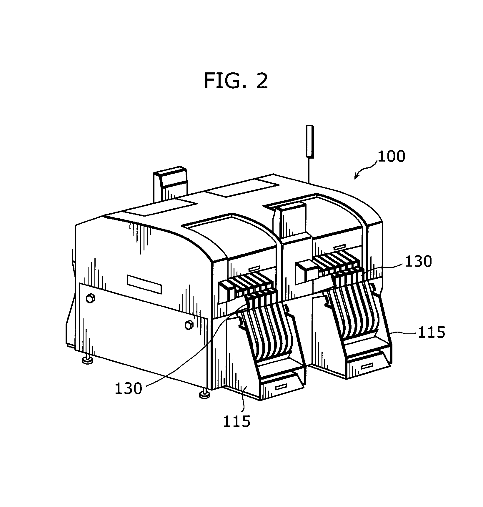
[0041]FIG. 2 is a diagonal view showing an appearance of the entire structure of a mounter 100 according to the present invention. The mounter 100 can form a production line for mounting electric components while transferring a circuit board (board) from an upper stream toward a lower stream.

[0042]The mounter 100 includes a component supplying unit 115 for supplying a mounter body 101 with the electric components to be mounted on a circuit board. The component supplying unit 115 has, as component holders, an array of plural tape feeders 130, each sending out a component tape as a component holder, or an array of plural parts feeders 130, each sending out the components held in a cassette.

[0043]FIG. 3 is a planar view showing a main structure of the mounter 100 of the present embodiment.

[0044]As shown in the diagram, the mounter 100 includes two sub facilities (a front sub facility 11...


PUM


Abstract

A holder identifying apparatus (140), which is detachably fitted to a mounter (100) that obtains components (500) from component holders for supplying the components (500) and that mounts the components (500) onto a board, and is used together with at least one component holder (150), includes a holder information storage unit (443) which stores information regarding the component holder (150).

Description

TECHNICAL FIELD[0001]The present invention relates to a holder identifying apparatus to be applied to a mounter for mounting components onto a board.BACKGROUND ART[0002]A conventional mounter for mounting components onto a board has multiple component holders as represented by tape feeders and parts feeders which are detachably fitted to a mounter body, and mounts various types of components which are held and supplied in a predetermined order by the respective component holders.[0003]Such component holder holds, in a component tape, a large number of components of the same type placed sequentially in a row in a length direction of the holder. In the case where a component needs to be supplied, the component holder winds off the component tape and takes off the cover, so that a component is placed in a position from which the component should be picked up.[0004]The operation of the component holder is controlled mainly by the mounter body using only ON-OFF signals based on an assign...

Claims


Application Information

Patent Timeline
IPC IPC(8): H05K13/04
CPCY10T29/5313H05K13/0417H05K13/0419H05K13/02H05K13/04
Inventor WADA, AKIFUMI
Owner PANASONIC CORP
Learn More