Heat exchanger having a counterflow evaporator

a technology of heat exchanger and evaporator, which is applied in the field of heat exchanger, can solve the problems of large size and high cost of heat exchangers that include evaporators heated by hot gases, evaporators that generate steam at a single pressure typically exhibit poor thermal efficiency, and systems and methods still suffer from drawbacks

Active Publication Date: 2008-05-08
LAIR LIQUIDE SA POUR LETUDE & LEXPLOITATION DES PROCEDES GEORGES CLAUDE
View PDF15 Cites 31 Cited by
  • Summary
  • Abstract
  • Description
  • Claims
  • Application Information

AI Technical Summary

Benefits of technology

[0005]In an effort to eliminate the above drawbacks of related art heat exchangers that include evaporators,

Problems solved by technology

Heat exchangers that include evaporators heated by hot gases typically suffer from relatively large size and high cost.
Further, evaporators that generate steam at a single pressure typically exhibit poor thermal efficiency because the hot gas contacts the tubing conveying the liquid being evaporated in a cross-flow or parallel fl

Method used


Image

  • Heat exchanger having a counterflow evaporator
  • Heat exchanger having a counterflow evaporator
  • Heat exchanger having a counterflow evaporator

Examples


Embodiment Construction

[0016]Embodiments of the present invention will be described hereinafter with reference to the accompanying drawings. In the following description, the constituent elements having substantially the same function and arrangement are denoted by the same reference numerals, and repetitive descriptions will be made only when necessary.

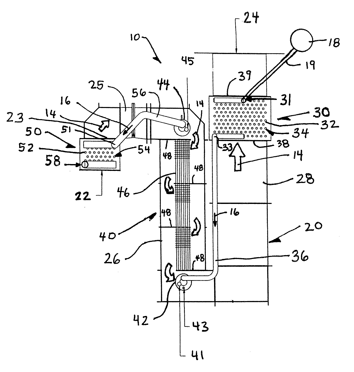
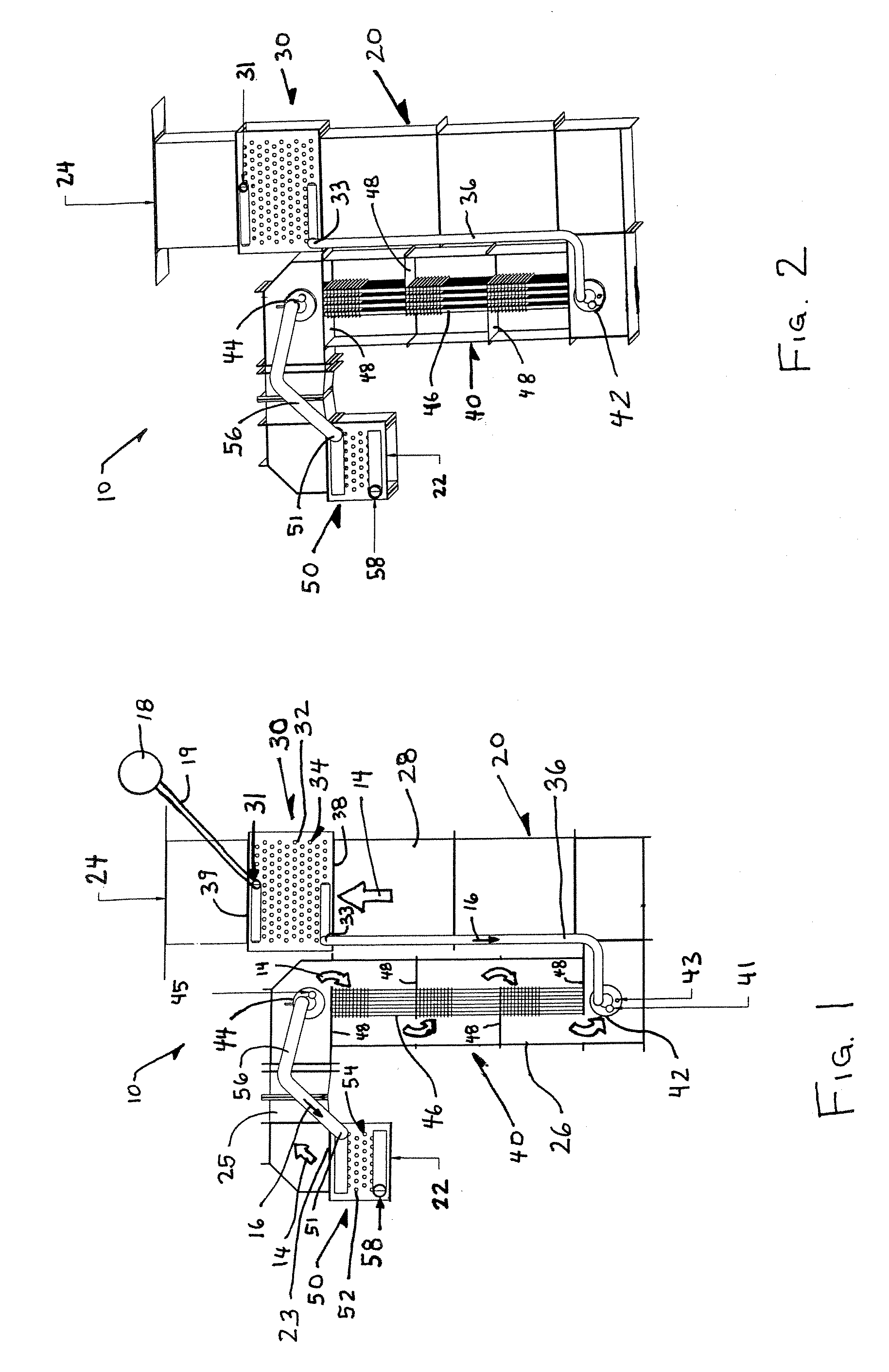
[0017]As depicted in FIGS. 1 and 2, the heat exchanger 10 of the present invention includes at least an evaporator 40. Alternatively, the heat exchanger 10 can also be provided with a first coil (referred to as an “economizer”) 30 to heat the evaporating fluid 16, which begins in a liquid phase, to a temperature below the boiling (saturation) temperature. The evaporating fluid 16 is pumped to the economizer 30 via a supply pipe 19 by a pump 18, and the evaporating fluid travels through a series of tubes 32 that extend across a portion of duct 20 of the heat exchanger upstream of an outlet 24 of the duct 20 carrying the heating gas 14 from the heating gas i...


PUM


Abstract

An evaporator including a lower drum, an upper drum, and at least one tube extending between the lower drum and the upper drum. The plurality of tubes have fluid passageways therein extending from the lower drum to the upper drum. A duct is provided having a heating gas passageway provided therein. The at least one tube extends through the heating gas passageway. The fluid passageways define an overall flow path from the lower drum to the upper drum extending in a direction substantially counter-current to an overall flow path defined by the heating gas passageway extending from a gas inlet of the heating gas passageway to a gas outlet thereof.

Description

BACKGROUND OF THE INVENTION[0001]1. Field of the Invention[0002]The present invention relates to a heat exchanger that includes a counterflow evaporator.[0003]2. Discussion of the Background[0004]Heat exchangers that include evaporators heated by hot gases typically suffer from relatively large size and high cost. Further, evaporators that generate steam at a single pressure typically exhibit poor thermal efficiency because the hot gas contacts the tubing conveying the liquid being evaporated in a cross-flow or parallel flow configuration at a single temperature, the saturation temperature at the pressure of interest. While previous systems and methods have attempted to improve upon steam boiler control and construction, these systems and methods still suffer from the drawback of cross-flow contact between the heating gas and the evaporating liquid.SUMMARY OF THE INVENTION[0005]In an effort to eliminate the above drawbacks of related art heat exchangers that include evaporators, the...

Claims


Application Information

Patent Timeline
IPC IPC(8): F01K7/42
CPCF22B21/16F22B31/02F22B37/40F22D1/06F22G1/02F22G7/12
Inventor LOMAX, FRANKLIN D.VAN DYKE, CHRISTOPHERMCCULLOUGH, EDWARD T.
Owner LAIR LIQUIDE SA POUR LETUDE & LEXPLOITATION DES PROCEDES GEORGES CLAUDE
Why Eureka
Try Eureka