Ink feed control method and ink feed control system

a control system and ink technology, applied in printing presses, office printing, printing, etc., can solve the problems of inability to produce normal printing products, difficult to make an accurate determination only with an image area ratio, and gradual increase in the printing density of printing products

Inactive Publication Date: 2008-05-08
KOMORI CORP
View PDF8 Cites 6 Cited by
  • Summary
  • Abstract
  • Description
  • Claims
  • Application Information

AI Technical Summary

Benefits of technology

[0011] In view of above-described circumstances, it is an object of the present invention to provide an ink feed control method and an ink feed control system, each of which makes it possible to control the number of feedings in accordance with the printing density or the ink film thickness of printing products.

Problems solved by technology

However, in the ink feeding method disclosed in Japanese Patent Application Laid-open Publication No. 2004-202947, it is difficult to make an accurate determination only with an image area ratio in the case of producing printing products with a thin ink film thickness, such as in the case of producing those by relief printing.
Accordingly, as long as printing products to be printed have a thin ink film thickness, even if these printing products to be printed have a large image area ratio, the amount of supplied ink often becomes too large, leading to a gradual increase in the printing density of the printing products.
Eventually, normal printing products cannot be produced.

Method used


Image

  • Ink feed control method and ink feed control system
  • Ink feed control method and ink feed control system
  • Ink feed control method and ink feed control system

Examples


first embodiment

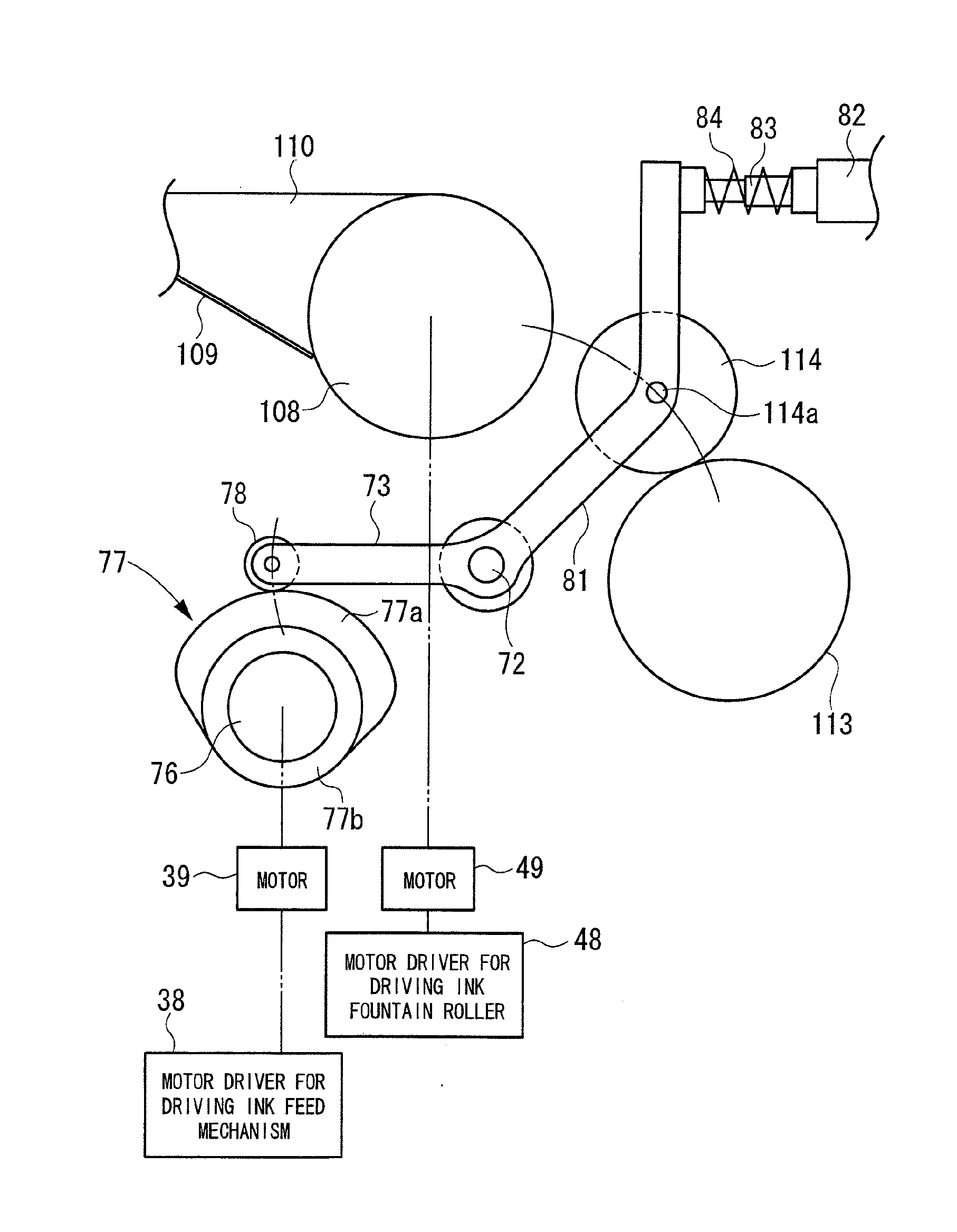
[0101] Firstly, descriptions will be given of the device configuration of an ink feed control system according to a first embodiment of the present invention. FIG. 1 is a side view showing principal parts of an inking device of a printing press according to the first embodiment of the present invention. In FIG. 1, the same reference numerals denote components that are the same as, or similar to, those described in the above-mentioned conventional technique shown in FIG. 48, and detailed descriptions of the same components will be omitted. An ink fountain roller 108 is provided as a roller on an upstream side in the ink transfer direction, while a distribution roller 113 is provided as a roller on the downstream side in the ink transfer direction. A ductor roller 114, and a ductor shaft 72, which serves as a swing fulcrum for swinging the ductor roller 114, are pivotally supported by the left and right frames (not illustrated) so as to rotate, between the ink fountain roller 108 and ...

second embodiment

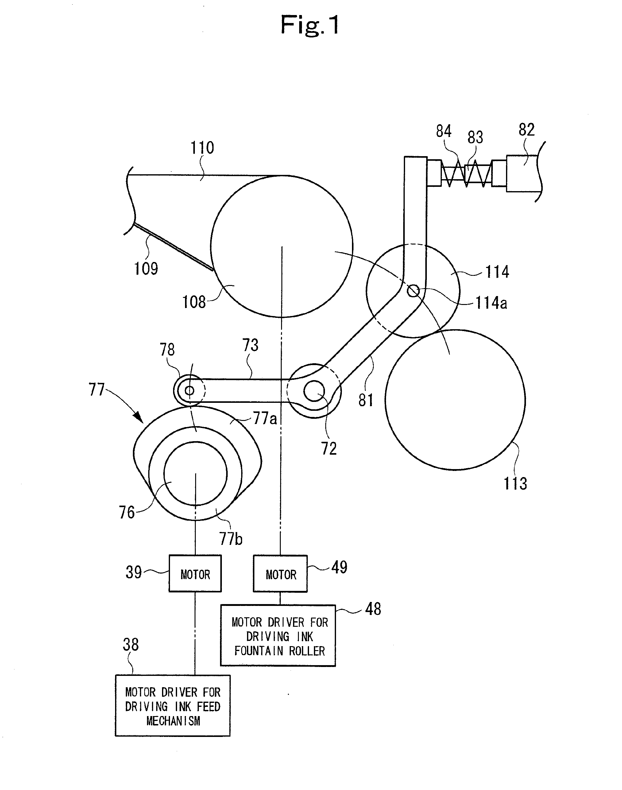
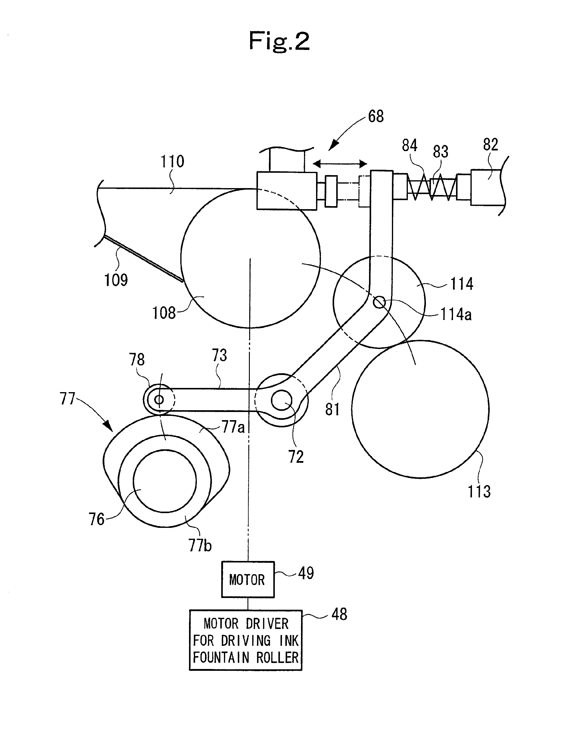
[0256] Firstly, descriptions will be given of the device configuration of an ink feed control system according to a second embodiment of the present invention. FIG. 2 shows a side view of principal parts of an inking device of a printing press according to the second embodiment of the present invention. In FIG. 2, the same reference numerals denote components that are the same as, or similar to, those described in the above-mentioned conventional technique shown in FIG. 48, and detailed descriptions of the same components will be omitted. In addition, in the second embodiment of the present invention, the basic driving of the ink feed mechanism is performed by using a cam 77 and the like, that is, the same as that in the first embodiment, and thus descriptions thereof will be omitted. The cam 77 is driven by a drive motor of the printing press. A ductor roller 114 and a ductor shaft 72, which serves as a swing fulcrum for swinging the ductor roller 114, are pivotally supported by le...

third embodiment

[0402] Firstly, descriptions will be given of the device configuration of an ink feed control system according to a third embodiment of the present invention. FIG. 2 shows a side view of principal parts of an inking device of a printing press according to the third embodiment of the present invention. In FIG. 2, the same reference numerals denote components that are the same as, or similar to, those described in the above-mentioned conventional technique shown in FIG. 48, and detailed descriptions of the same components will be omitted. In addition, in the third embodiment of the present invention as well, the basic driving of the ink feed mechanism is performed by using a cam 77 and the like, that is, the same as that in the first embodiment, and thus descriptions thereof will be omitted. The cam 77 is driven by a drive motor of the printing press. A ductor roller 114 and a ductor shaft 72, which serves as a swing fulcrum for swinging the ductor roller 114, are pivotally supported ...


PUM


Abstract

An ink feed control method for a printing press in which ink, supplied to an ink fountain roller from a gap between each ink fountain key and the ink fountain roller by the rotation of the ink fountain roller, is supplied to the printing plate by swing operation of an ink ductor roller, so that a print is eventually made on a print sheet with the ink supplied to the printing plate, the method including the steps of: measuring any one of the density and the ink film thickness of a first printing product made by the printing press; and controlling the number of times of the swing operation of the ink ductor roller relative to the rotation of the printing press in accordance with the value of the measured one of the density and the ink film thickness of the first printing product.

Description

BACKGROUND OF THE INVENTION [0001] 1. Field of the Invention [0002] The present invention relates to an ink feed control method and an ink feed control system for a printing press. [0003] 2. Description of the Related Art [0004] A printing press is provided with an inking device for supplying ink to a printing plate. FIG. 48 shows a schematic side view of an inking device 100 of a general printing press. Descriptions will be given below of the inking device 100 with reference to FIG. 48. Reference numeral 101 denotes a plate cylinder, which is pivotally supported by an unillustrated pair of left and right frames, and a plate for printing is mounted on the circumferential surface of the plate cylinder 101. Two pairs of ink form rollers 103 are detachably in contact with the surface of the plate cylinder 101. Each pair of ink form rollers 103 are supported by a corresponding one of a pair of oscillating rollers 102 with an arm in between. In addition, three distribution rollers 104 ar...

Claims


Application Information

Patent Timeline
Patent Type & Authority Applications(United States)
IPC IPC(8): B41F1/46
CPCB41F31/12B41F33/0045B41F31/14
Inventor KUSAKA, AKEHIRONUMAUCHI, HIROMITSU
Owner KOMORI CORP
Why Eureka
Try Eureka