
System and Method for Detecting Distribution Transformer Overload

a technology of distribution transformers and systems, applied in the field of methods and apparatus for detecting power distribution parameters, can solve the problems of power overload, adversely affecting the life and operation of distribution transformers, and replacement costs and maintenance costs of distribution transformers

Inactive Publication Date: 2008-05-08
CURRENT TECH
View PDF25 Cites 118 Cited by
  • Summary
  • Abstract
  • Description
  • Claims
  • Application Information

AI Technical Summary

Problems solved by technology

Thus, the replacement costs and maintenance costs for distribution transformers can be a significant factor in the cost of power distribution.
One factor that adversely affects the life and operation of a distribution transformer is a power overload.
Overloading a given distribution transformer may reduce the useful life of the transformer.
In particular, an overload increases the temperature of the transformer windings, which in turn increases the temperature of the transformer insulation.
A breakdown of the transformer's insulation, such as from the increased temperature, decreases the useful life of the transformer and increases the chances of a transformer failure.
In fact the cause of most transformer failures is a breakdown of the insulation, so anything that adversely affects the insulating properties inside the transformer reduces transformer life.
Overloading a distribution transformer is one of the prime causes of insulation breakdown.
One challenge to the efficient maintenance of a distribution transformer is that an overload can not be detected and monitored directly.
Commonly however, it is when the transformer fails that an overload condition is specifically identified.
However, the specific size and rating of a specific transformer is not directly monitored.

Method used


Image

  • System and Method for Detecting Distribution Transformer Overload
  • System and Method for Detecting Distribution Transformer Overload
  • System and Method for Detecting Distribution Transformer Overload

Examples


Embodiment Construction

[0023]In the following description, for purposes of explanation and not limitation, specific details are set forth, such as particular networks, communication systems, computers, terminals, devices, components, techniques, data and network protocols, power line communication systems (PLCSs), software products and systems, enterprise applications, operating systems, development interfaces, hardware, etc. in order to provide a thorough understanding of the present invention.

[0024]However, it will be apparent to one skilled in the art that the present invention may be practiced in other embodiments that depart from these specific details. Detailed descriptions of well-known networks, communication systems, computers, terminals, devices, PLCSs, components, techniques, data and network protocols, software products and systems, operating systems, development interfaces, and hardware are omitted so as not to obscure the description of the present invention.

[0025]According to an embodiment ...


PUM


Abstract

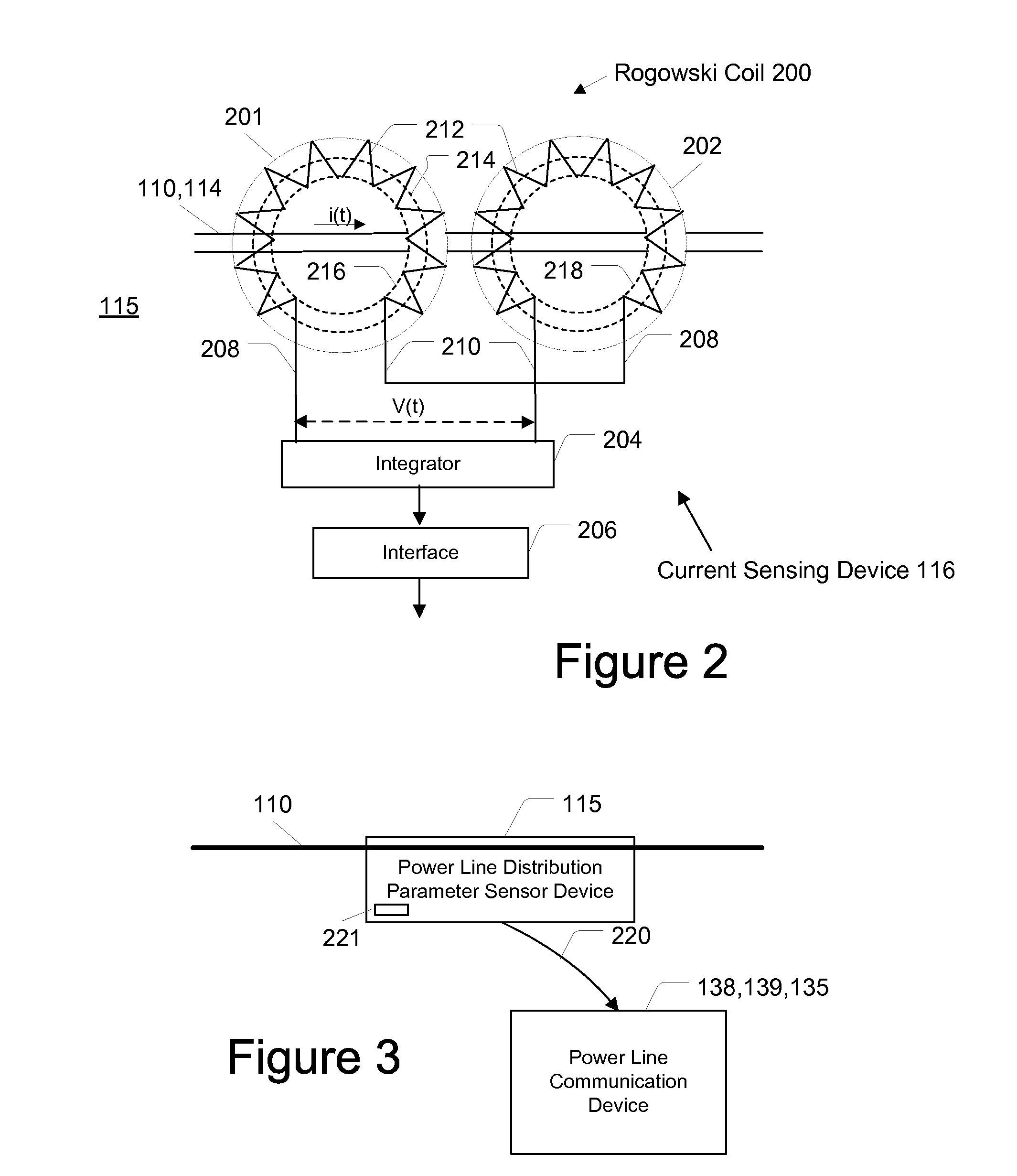
A system, device, and method of detecting an overload condition of a distribution transformer that supplies power to one or more customer premises via a low voltage subnet is provided. In one embodiment, the method comprises determining the power output of the transformer; storing in a memory a threshold power value for the transformer; determining whether the power output exceeds the threshold power value; and, if the output power exceeds the threshold power value, providing a notification. Providing the notification may include wirelessly transmitting the notification and / or transmitting the notification over a medium voltage power line. The low voltage subnet may comprise a low voltage feeder that supplies power to a plurality of low voltage supply lines that extend to the customer premises in which case determining the output power may comprise measuring a voltage of the low voltage feeder and measuring a current traversing the low voltage feeder. The method may also comprise storing in the memory a plurality of threshold power values associated with a plurality of transformers, such as different models of transformers; receiving data of the power output of a multitude of transformers; and determining whether the power output of each of the multitude of transformers exceeds the threshold value associated with the transformer, which steps may be performed at a central computer system such as a power line server.

Description

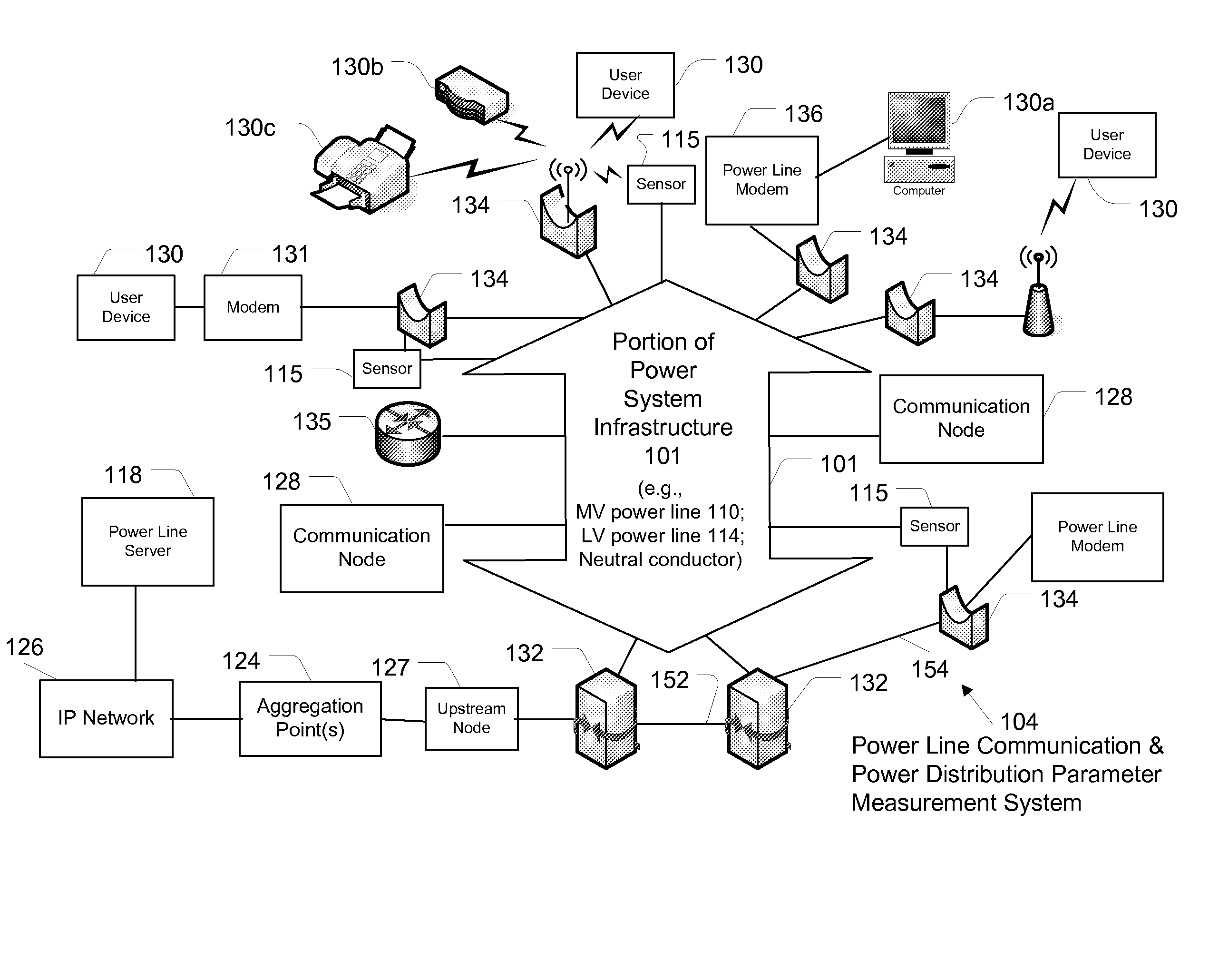
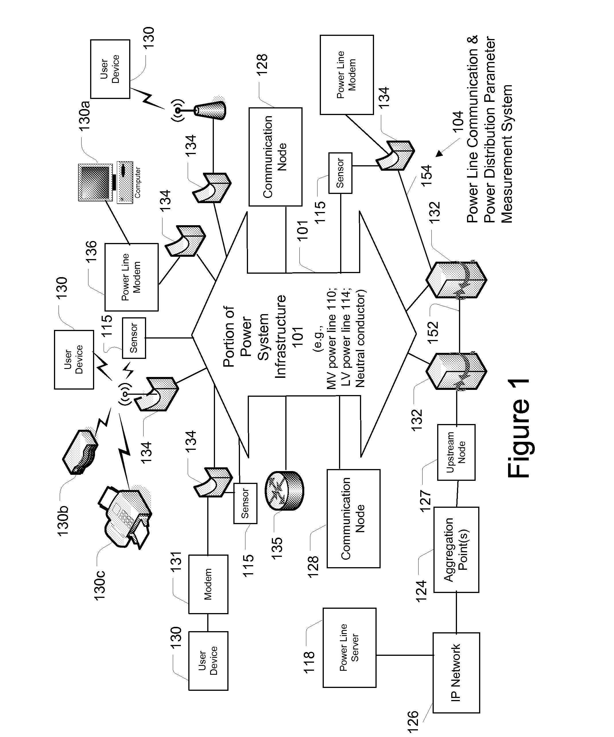
CROSS REFERENCE TO RELATED APPLICATIONS[0001]This application is a continuation-in-part of, and claims priority to, U.S. patent application Ser. No. 11 / 555,740 filed Nov. 2, 2006, which is incorporated herein by reference in its entirety.FIELD OF THE INVENTION[0002]The present invention generally relates to methods and apparatus for monitoring power distribution parameters, and more particularly to methods and apparatus for detecting distribution transformer overload.BACKGROUND OF THE INVENTION[0003]Distribution transformers are parts of the power system infrastructure. The power system infrastructure includes power lines, transformers and other devices for power generation, power transmission, and power delivery. A power source generates power, which is transmitted along high voltage (HV) power lines for long distances. Typical voltages found on HV transmission lines range from 69 kilovolts (kV) to in excess of 800 kV. The power signals are stepped down to medium voltage (MV) power...

Claims


Application Information

Patent Timeline
Patent Type & Authority Applications(United States)
IPC IPC(8): G01R19/165G08B21/00
CPCG01R19/16547G06Q50/06G01R19/2513
Inventor DEAVER, BRIAN J.RADTKE, WILLIAM O.
Owner CURRENT TECH
Learn More