Pallet puller tool

a puller and tool technology, applied in the field of material handling tools, can solve the problem of relatively high cost of machines

Inactive Publication Date: 2008-05-08
B A C INDS
View PDF14 Cites 28 Cited by
  • Summary
  • Abstract
  • Description
  • Claims
  • Application Information

AI Technical Summary

Benefits of technology

[0007]In accordance with the present invention, there is provided a tool for grasping and pulling articles, such as wooden pallets. The tool includes a base member that is supported from the ground by a pair of wheels. An elongated handle having first and second ends, the first end being connected to the base plate and a second end that connects to a grip member that extends transversely to the longitudinal axis of the handle. Coupled to the base member is a pair of jaw members, each having first and second end portions. The pair of jaw members is pivotally joined to one another at a location that is offset from the first and second end portions. More particularly, the pair of jaw members is coupled to the base member through first and second linkages that are pivotally coupled at a first end to the base member. The first linkage is pivotally coupled at its second end to the second end portion of one of the pair of jaw members. The second linkage is pivotally coupled at its second end to the second end portion of the other of the pair of jaw membe

Problems solved by technology

While a forklift or pallet-jack could be used, such machines are relatively costly and should be

Method used


Image

  • Pallet puller tool
  • Pallet puller tool
  • Pallet puller tool

Examples


Embodiment Construction

[0013]Certain terminology will be used in the following description for convenience in reference only and will not be limiting. The words “upwardly”, “downwardly”, “rightwardly” and “leftwardly” will refer to directions in the drawings to which reference is made. The words “inwardly” and “outwardly” will refer to directions toward and away from, respectively, the geometric center of the device and associated parts thereof. Said terminology will include the words above specifically mentioned, derivatives thereof and words of similar import.

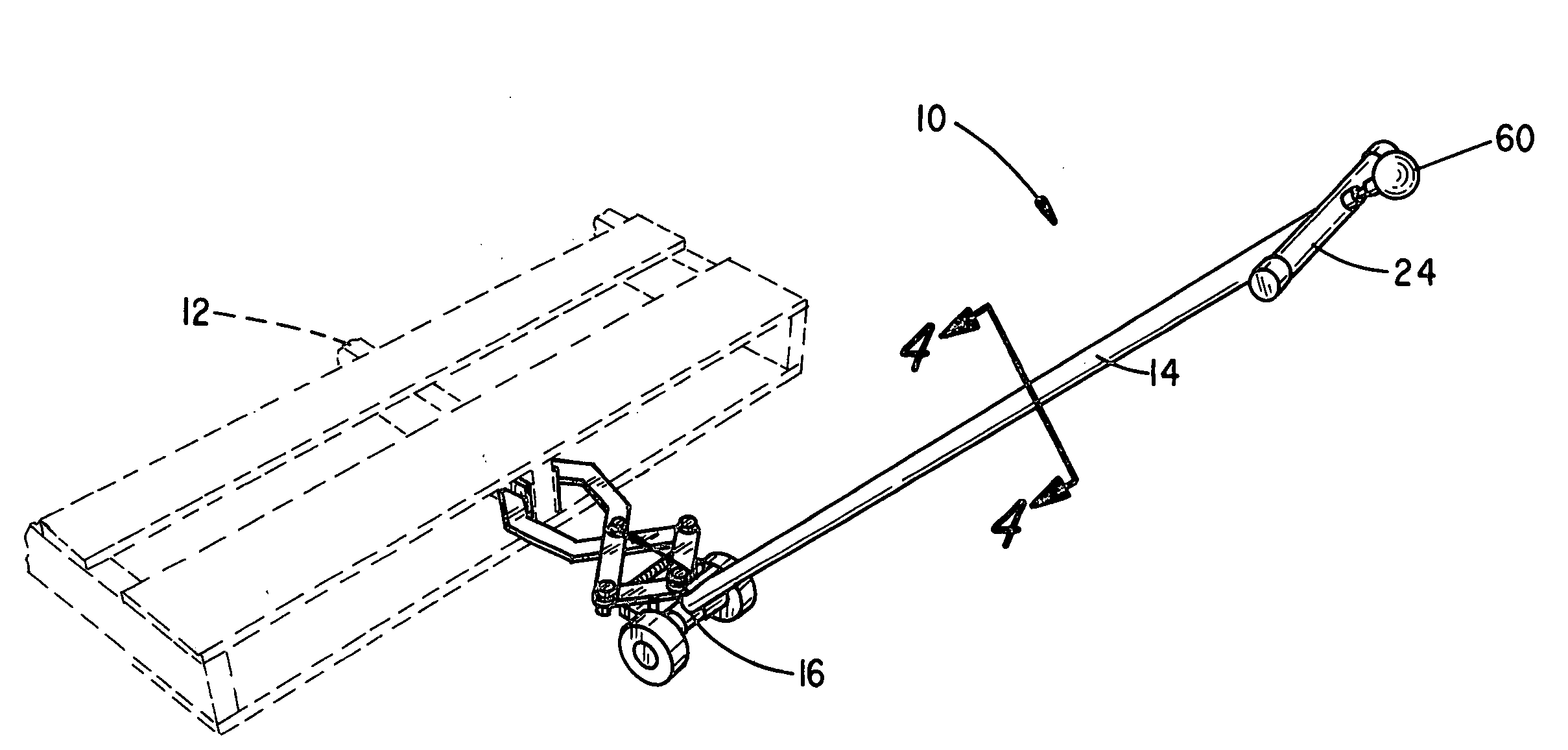
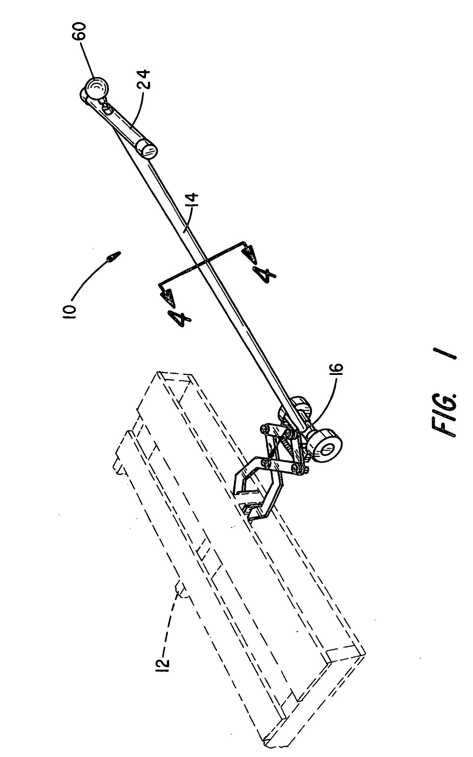
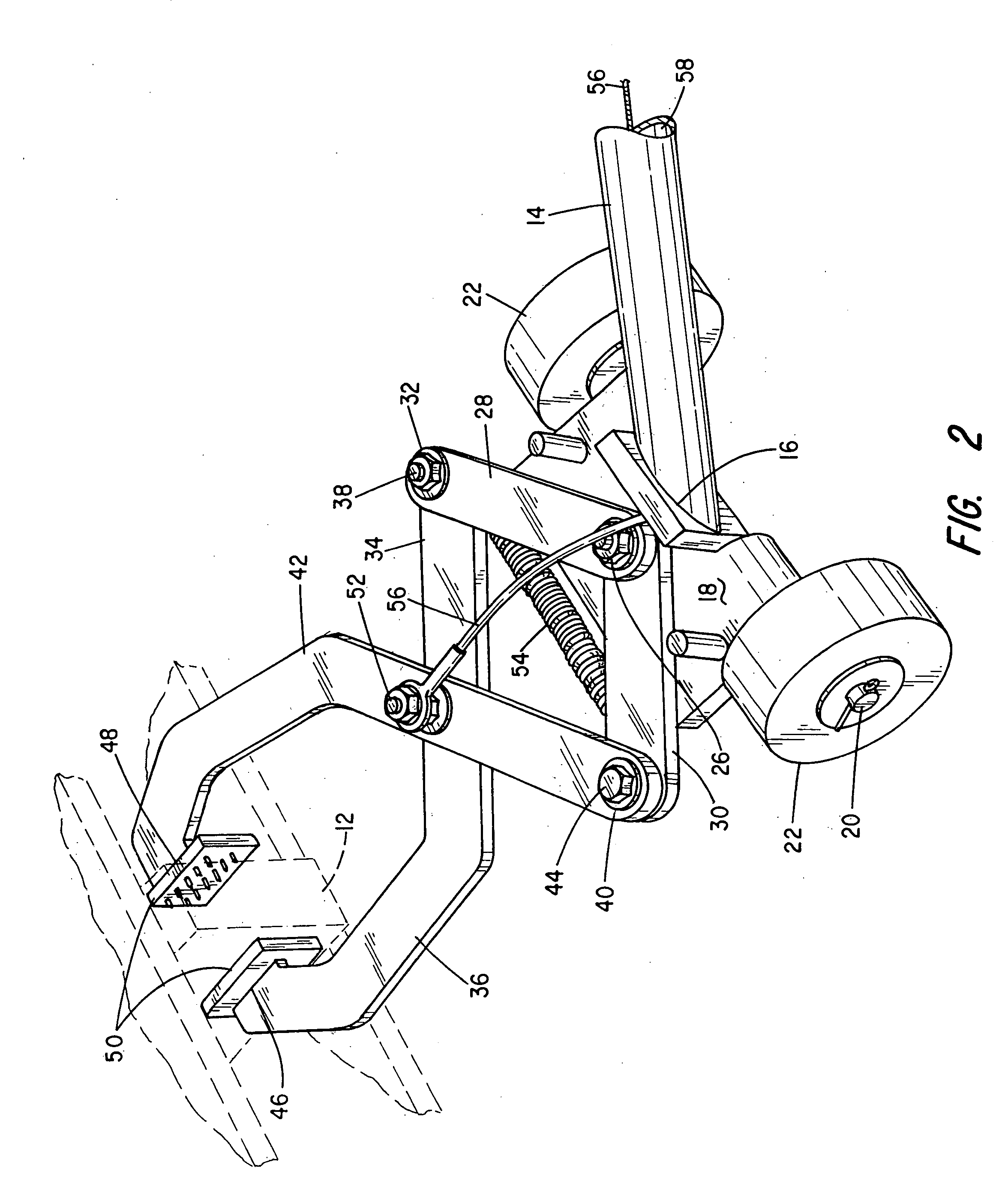
[0014]Referring to FIG. 1, there is indicated generally by numeral 10 a pallet-puller tool constructed in accordance with the present invention. It is shown as being positioned about a center stringer 12 of a standard wooden pallet that is shown in ghost-line. The tool itself includes an elongated handle 14 that is preferably tubular that attaches at a first end 16 to a base plate 18 that is best seen in the view of FIG. 2. Projecting laterally out...


PUM


Abstract

A tool for dragging wooden shipping pallets along the ground comprises a wheel-mounted base member that has an elongated handle attached to it. The base member supports a pair of jaw members that is pivotally joined to one another along with a pair of linkages pivotally joined at one end to the base member and at the other ends to the end portions of the jaw members. A tension spring is connected between the pivot points where the linkages join to the end portions of the jaw members to normally urge the jaws to be closed relative to one another. A cable or cord attaches at one end of the pivot joint between the two jaw members and extends along the length of the handle to a pull knob. Tension on the cable or cord acts against the force of the spring to open the jaw members.

Description

BACKGROUND OF THE INVENTION[0001]I. Field of the Invention[0002]This invention relates generally to material handling tools, and more particularly to a tool for grasping and dragging wooden shipping pallets along a floor surface.[0003]II. Discussion of the Prior Art[0004]In shipping and receiving departments of factories, warehouses and retail establishments, products are often contained on wooden pallets so that a forklift machine can readily pick up and transport the pallet and products from one point to another. Another well-known machine for manipulating pallets is the so-called “pallet-jack”. The pallet-jack machine rides on wheels and has a pair of tines or forks that are spaced apart by a distance dictated by the dimensions of the pallet to be carried. An elongated handle can be pumped up-and-down to hydraulically or otherwise elevate the forks and raise a pallet from the floor so that the pallet-jack can be easily pulled. The Fahnestock U.S. Pat. No. 1,115,796 is an example ...

Claims


Application Information

Patent Timeline
IPC IPC(8): B62B1/06B62B1/26
CPCB62B1/06B62B2203/44B62B5/0083B62B1/268
Inventor OBERG, JAMES D.
Owner B A C INDS
Why Eureka
Try Eureka