Fuel pump and filter assembly

a technology of fuel pump and filter assembly, which is applied in the direction of piston pump, positive displacement liquid engine, separation process, etc., can solve the problems of limiting the efficiency of such pump assemblies, undesirably heating fuel, and current fuel pump modules are axially too long to be packaged in such a location, so as to reduce or eliminate pump flow-through losses, improve fuel pumping efficiency, and improve the effect of fuel vapor venting

Inactive Publication Date: 2008-05-08
TI GRP AUTOMOTIVE SYST LLC
View PDF22 Cites 9 Cited by
  • Summary
  • Abstract
  • Description
  • Claims
  • Application Information

AI Technical Summary

Benefits of technology

[0008]At least some of the objects, features and advantages that may be achieved by at least certain embodiments of the invention include a fuel pump and filter assembly that is readily adaptable to various fuel pump modules, fuel tanks, and vehicle applications; routes pressurized fuel away from an electric motor portion of the assembly; reduces or eliminates pump flow-through losses; increases fuel pumping efficiency; decreases heat transferred to the fuel before it is discharged from the fuel pump assembly; improves the venting of fuel vapor from the fuel pump; lowers the electric current draw of the fuel pump; eliminates costly seals between a pump and a housing; allows for a reduction in axial height of a fuel pump module compared to prior art designs; enables an electrical connector of a fuel pump assembly to extend out of a fuel tank; eliminates one or more wiring harnesses; and is of relatively simple design, economical manufacture and assembly, rugged, durable, reliable, and in service has a long useful life.

Problems solved by technology

While generally effective at cooling the electric motor, pump assemblies of this type undesirably heat the fuel.
Such windage losses limit the efficiency of such pump assemblies.
But, current fuel pump modules are axially too long to be packaged in such a location.

Method used


Image

  • Fuel pump and filter assembly
  • Fuel pump and filter assembly
  • Fuel pump and filter assembly

Examples


Embodiment Construction

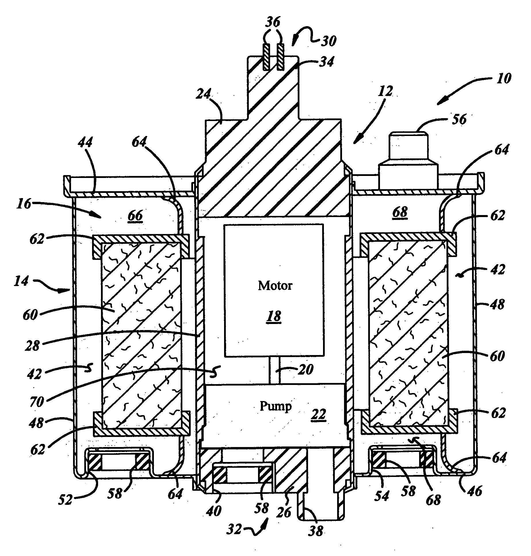
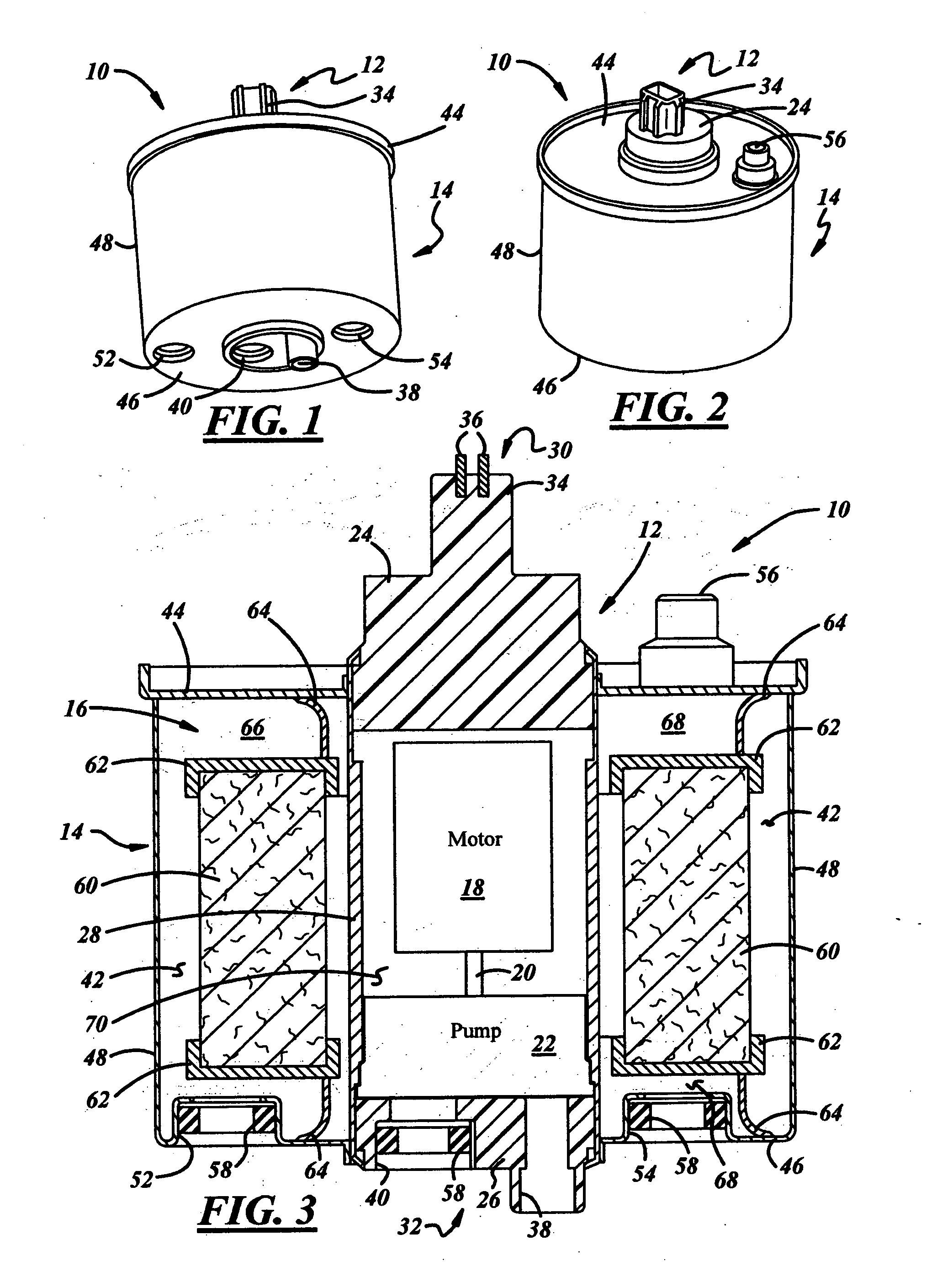
[0019]Referring in more detail to the drawings, FIGS. 1 through 3 illustrate a presently preferred form of a fuel pump and filter assembly 10 for drawing fuel from within a fuel tank (not shown) and pressurizing and filtering the fuel for sending it to an engine (not shown). As best shown in FIG. 3, the assembly 10 includes a fuel pump assembly 12 for drawing and pressurizing the fuel, a housing 14 for carrying the fuel pump assembly 12, and a filter 16 carried in the housing 14 for filtering the pressurized fuel received from the fuel pump assembly 12. The assembly 10 may be used alone or in conjunction with a fuel pump module (not shown) for insertion into the fuel tank.

[0020]The fuel pump assembly 12 may be any suitable pumping device, such as an electromechanical pumping device, that pressurizes fuel for delivery to an upstream or inlet side of the filter 16. The fuel pump assembly 12 is centrally located with respect to the filter 16 and housing 14 such that the filter 16 and t...


PUM

PropertyMeasurementUnit
shapeaaaaaaaaaa
pressureaaaaaaaaaa
electrical poweraaaaaaaaaa

Abstract

A fuel pump and filter assembly includes a housing supporting a filter in a filter chamber, which is at least partially defined by first and second end walls, an outer wall extending therebetween, and an inner side wall disposed radially inwardly of the outer side wall. A fuel pump assembly is carried by the housing radially inwardly of the inner side wall and includes a sleeve that extends from the first end wall of the housing to the second end wall of the housing.

Description

FIELD OF INVENTION[0001]The present invention relates generally to fuel pumps and more particularly to fuel pump modules for placement in fuel tanks.BACKGROUND OF THE INVENTION[0002]In-tank fuel pump modules are used in automotive fuel delivery systems to draw fuel from a fuel tank and supply the fuel under pressure for delivery to an engine. These modules usually include a fuel reservoir disposed within the fuel tank and carried by a mounting plate or flange closing an opening in an upper wall of the tank. The reservoir holds a relatively small quantity of fuel, and typically includes a reservoir inlet in communication with the interior of the fuel tank.[0003]The module typically includes an electric fuel pump assembly having a pump inlet in one end communicating with the reservoir downstream of the reservoir inlet, and a pump outlet in another end upstream of the reservoir outlet. The fuel pump assembly draws fuel from within the reservoir through the fuel pump inlet and delivers ...

Claims


Application Information

Patent Timeline
Patent Type & Authority Applications(United States)
IPC IPC(8): F04B17/00
CPCF02M37/10F02M2037/225F02M37/22F02M37/44F02M37/50
Inventor CRARY, LYNWOOD F.DASILVA, ANTONIO J.KUPERUS, PETER P.
Owner TI GRP AUTOMOTIVE SYST LLC
Why Eureka
Try Eureka