Implant, implantation device, implantation method

Active Publication Date: 2008-05-08
WOODWELDING
View PDF17 Cites 117 Cited by
  • Summary
  • Abstract
  • Description
  • Claims
  • Application Information

AI Technical Summary

Benefits of technology

[0005] A first aspect of the invention provides an implant suitable for being anchored in an opening in bone tissue with the aid of mechanical vibration. The implant is able to be compressed in the direction of a chosen compression axis with the effect of a local enlargement of a distance between a peripheral implant surface and the c

Problems solved by technology

There are situations however, in which anchoring of implants in hard tissue by mechanical vibrations according to the state-of-the-art technology does not suffice or in which, fo

Method used


Image

  • Implant, implantation device, implantation method
  • Implant, implantation device, implantation method
  • Implant, implantation device, implantation method

Examples


Embodiment Construction

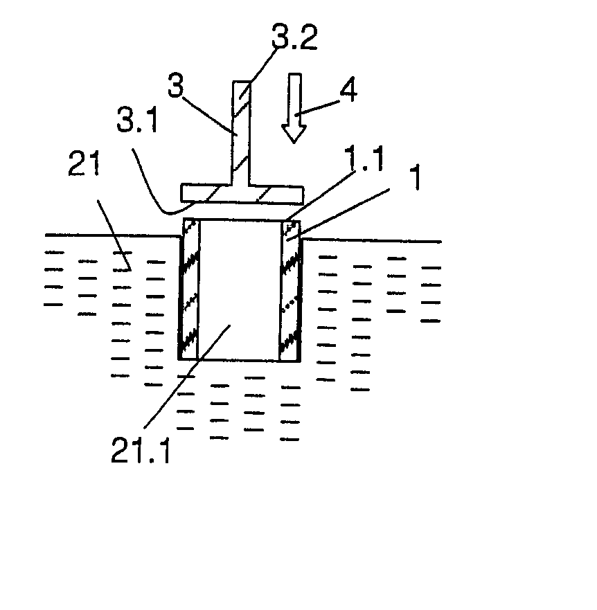
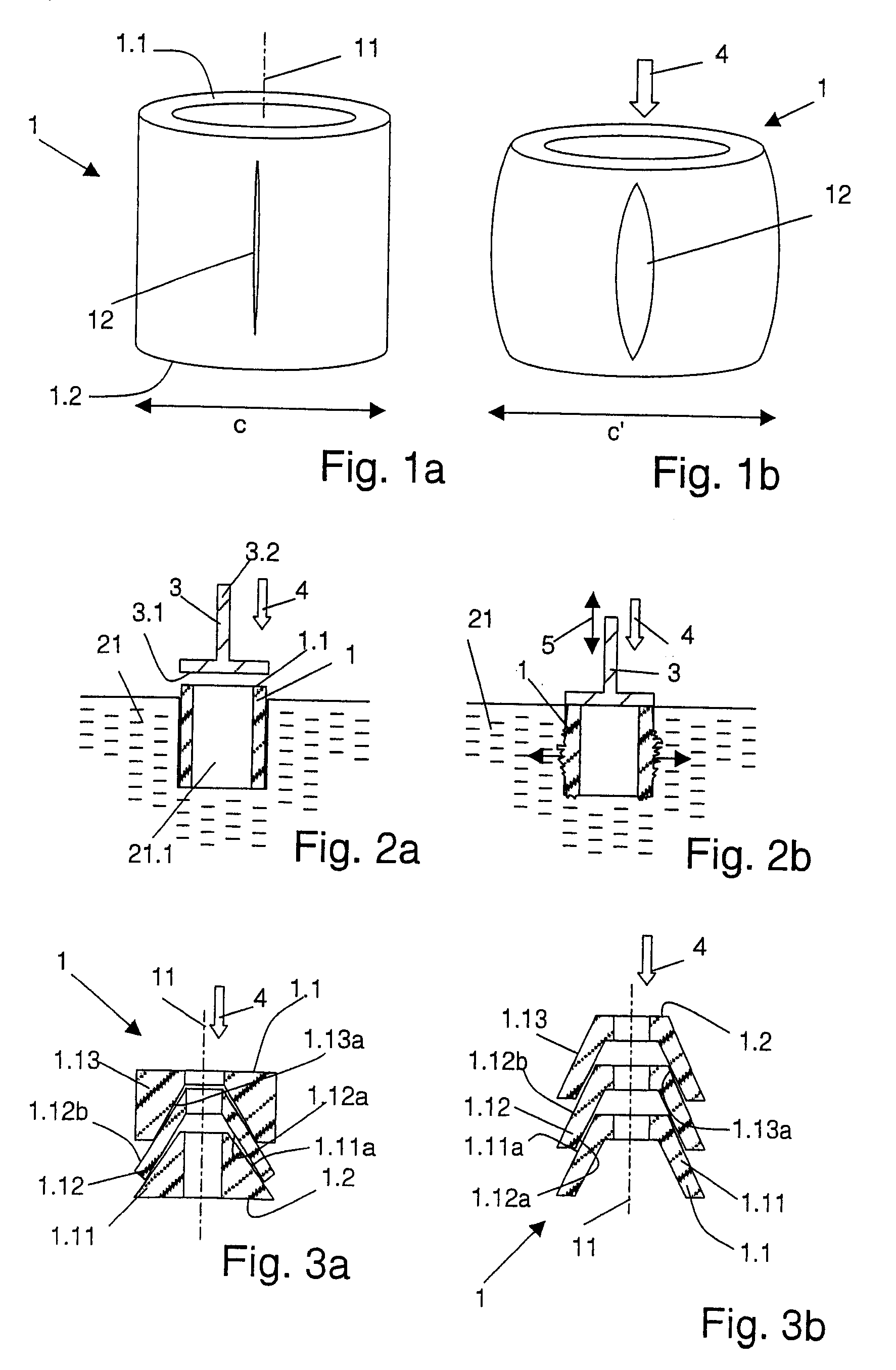
[0095] The implant 1 according to FIG. 1a is a first example of an implant according to the first aspect of the invention. The implant is essentially tubular, consists of a thermoplastic material, and comprises a proximal end face 1.1 and a distal end face 1.2. The implant further comprises at least one slot 12 extending approximately parallel to the axis 11 of the implant; advantageously there are two, three or more than three slots arranged approximately equidistantly. Due to the slot or slots 12 the implant is compressible by a compressing force 4 acting parallel to its axis (according to FIG. 1a, the axis 11 of the tubular implant is also its compression axis). The implant is depicted in a compressed state in FIG. 1b.

[0096] It is obvious that for achieving the desired compression, a force must act upon the implant from two opposite sides (“force and counterforce”), wherein the counterforce is often exerted by a stop face. In the embodiment according to FIGS. 1a and 1b compressi...


PUM


Abstract

An implant suitable for being anchored with the aid of mechanical vibration in an opening provided in bone tissue. The implant is compressible in the direction of a compression axis under local enlargement of a distance between a peripheral implant surface and the compression axis. The implant includes a coupling-in face which serves for coupling a compressing force and the mechanical vibrations into the implant, which coupling-in face is not parallel to the compression axis. The implant also includes a thermoplastic material which, in areas of the local distance enlargement, forms at least a part of the peripheral surface of the implant.

Description

BACKGROUND OF THE INVENTION [0001] The invention lies in the field of medical technology and concerns implants, surgical devices, and surgical methods. It especially concerns implants suitable for being anchored in hard tissue, in particular in bone tissue, with the aid of mechanical vibrations, through which a, for example, thermoplastic material provided on the implant is liquefied in places where it is in contact with the hard tissue. [0002] Such implants and corresponding methods for anchoring these in bone tissue are known from the publications WO 02 / 069 817, WO 2004 / 017 857 and WO 2005 / 079 696. The thermoplastic material of such implants is liquefied by mechanical vibrations while being pressed against osseous material, so that it is pressed into cavities (pores, artificially produced cavities) of the osseous material. This results in a most effective anchoring of the implant in bone tissue. [0003] There are situations however, in which anchoring of implants in hard tissue by ...

Claims


Application Information

Patent Timeline
IPC IPC(8): A61F2/28A61B17/20
CPCA61F2002/30904A61B2017/0424A61F2230/0069A61F2002/30973A61B2017/042A61F2250/0063A61B17/0401A61F2002/3611A61F2002/30143A61C8/0016A61F2220/0025A61B17/8822A61B17/8872A61F2002/30136A61F2002/3023A61F2002/30599A61F2002/30579A61F2002/30235A61F2/4603A61F2002/30604A61F2002/30405A61F2230/0004A61F2/2875A61B2017/00004A61F2220/0008A61F2002/30457A61F2230/0067A61F2002/30065A61C8/0012A61F2002/3052A61F2220/0058A61F2002/30205A61F2002/30561A61F2210/0071A61F2002/3021A61F2230/0017A61F2230/0063A61F2/30749A61F2/3601A61F2220/0033A61F2002/365A61F2002/30332A61F2002/30377A61C8/0018A61F2002/30217A61B17/686A61F2002/4683A61F2002/30309A61F2002/3625A61F2/0811A61B17/68A61F2220/0016A61F2002/30451A61F2002/30367A61B17/844A61B2017/0403A61F2/3609A61F2002/0835A61F2002/0888
Inventor AESCHLIMANN, MARCELTORRIANI, LAURENTLEHMANN, MARIOMAYER, JORG
Owner WOODWELDING
Why Eureka
Try Eureka