
Space Structure

a space structure and structure technology, applied in the field of space structures, can solve problems such as difficulty in redesign

Active Publication Date: 2008-05-15
UCHIDA YOKO LTD
View PDF20 Cites 35 Cited by
  • Summary
  • Abstract
  • Description
  • Claims
  • Application Information

AI Technical Summary

Benefits of technology

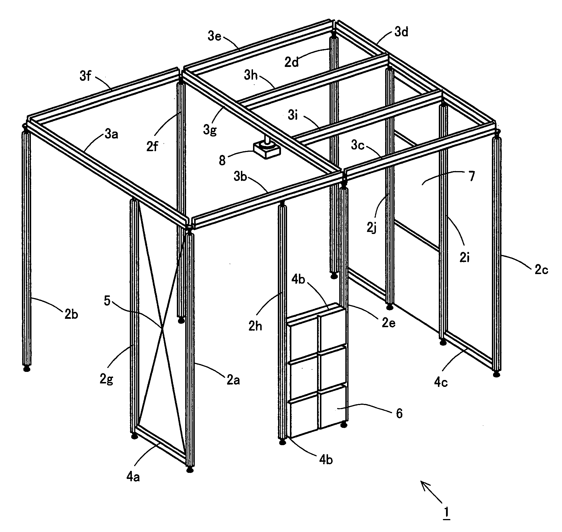
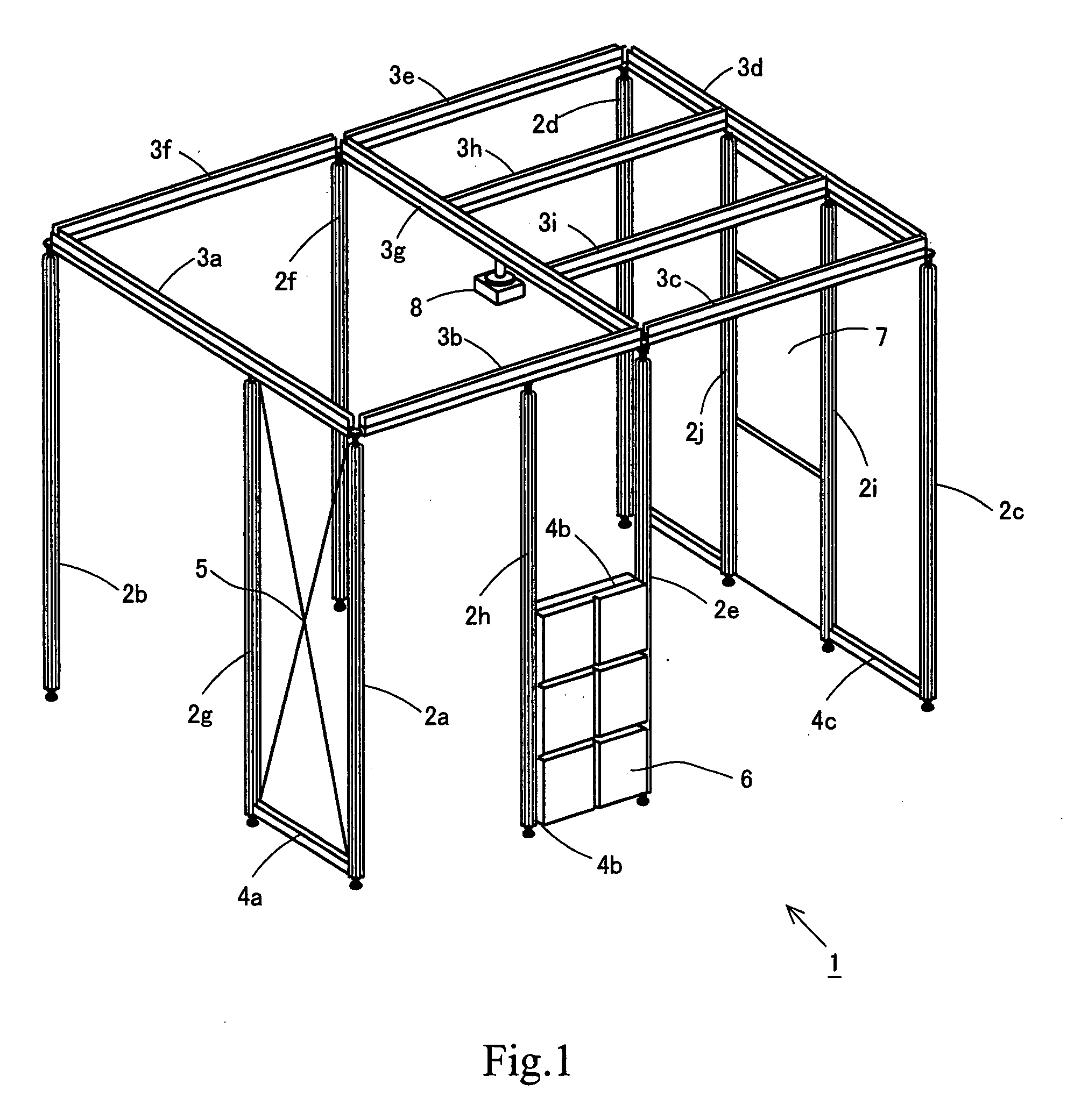
[0007]The present invention has been made in view of the above described problems, and has as an object to make it possible to flexibly adapt a space structure in which information apparatuses are used to newly emerging information apparatuses and replacement of information apparatuses and to design a new space structure easily.
[0081]According to the flat plate fixing device according to the present invention, it is possible to freely change the fixing position of a flat plate, among members composing a space structure, that functions as a wall or partition.

Problems solved by technology

However, conventional space structures have been designed taking into consideration specific information apparatuses as described above, and it is very difficult to redesign them.

Method used


Image

  • Space Structure
  • Space Structure
  • Space Structure

Examples


second embodiment

[0183]A brace that can be used in the space structure 1 described in the first embodiment will be described with reference to drawings.

[0184]FIG. 36 shows a configuration of a brace receiving member, a brace connection member and a brace structure 5 using them according to the present invention. As shown in FIG. 36, the brace structure 5 according to the present invention is constructed by two braces 430a, 430b arranged crosswise, brace connection members 420a, 420b attached to both ends of the braces 430a, 430b, and brace receiving members 410 attached to the brace connection members 420a, 420b. The brace receiving member 410 is attached to a pole having a rectangular frame structure or the like. Referring to details of the configuration of the braces 430a, 430b, one brace 430a is connected to the hooks 411a that are depicted as the front side hooks of the brace receiving members 410 (see the upper left member in FIG. 36) by means of the brace connection members 420a, 420b. The oth...

third embodiment

[0195]Next, a detailed description will be made of a way of attaching a flat panel such as a screen 8 or a glass plate to poles 2 and / or beams 3 of the space structure 1 according to the first embodiment using a flat plate mounting device.

[0196]FIG. 41 is a perspective view showing a state in which flat plate mounting devices are attached to a pole 2. FIG. 42 is a plan view showing the same state. As shown in FIG. 41, each flat plate mounting device is composed of a flat plate holding member 510, a bracket 90 fixedly attached on the pole 2 and an adjuster 530 set between the flat plate holding member 510 and the bracket 90. Here, the flat plate is a glass panel 540, which is held by the flat plate holding member 510. The flat plate holding member 510 is connected to the adjuster 530, which in turn is connected to the bracket 90. In the illustrated case, two brackets 90 are respectively attached to opposite sides of the pole 2, and two glass panels 540 are arranged on the front side ...


PUM


Abstract

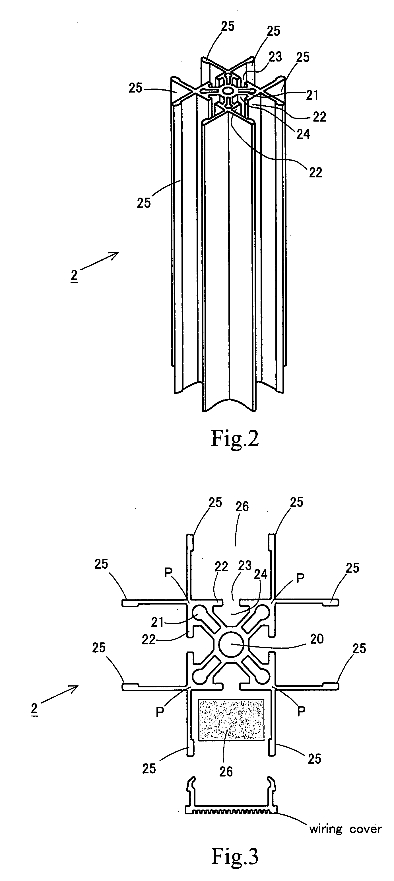
A space structure is composed of a post member and a horizontal beam member. The post member has a post member groove portion that constitutes a semi-closed space having an opening portion in a cross section of the post member and extends along its axial direction. The horizontal beam member has one or plurality of horizontal beam member groove portions each of which constitutes a semi-closed space having an opening portion in a cross section of the horizontal beam member and extends along its axial direction. Connection of the post member and the horizontal beam member is achieved by connecting connection means that can be moved inside the post member groove portion that the post member has or the horizontal beam member groove portion that the horizontal beam member has to an arbitrary position along its axial direction and can be fixed at that position, with the post member or the horizontal beam member through the opening portion of the post member groove portion or the horizontal beam member groove portion. Thus, it is possible to design a new space structure easily to flexibly adapt it to newly developed information apparatuses or replacement of information apparatuses.

Description

TECHNICAL FIELD[0001]The present invention relates to a space structure that defines a space used to exhibit information apparatuses and panels etc. in a place such as an office or an exhibition hall and a connecting device for connecting members in such a space structure.BACKGROUND ART[0002]Various technologies for constructing a space to facilitate utilization of the space by many people in, for example, an office or the like have been laid open. For example, a technology of constructing a sturdy space structure constructed by connecting poles and frame members without damaging an office or the like has been laid open (see, for example, Japanese Patent Application Laid-open No. 2003-138771). This technology teaches a minimum common space structure constructed by three poles and two frame members, where the frame members form an inner angle of 120 degrees.[0003]To use information apparatuses in a space in an office or the like, it is important to arrange wiring such as power supply...

Claims


Application Information

Patent Timeline
Patent Type & Authority Applications(United States)
IPC IPC(8): E04H12/10
CPCE04B1/58F16B7/185E04B2/761E04B2/78E04B2/7818E04B2001/2496E04B2002/749E04C3/02E04C3/06E04C2003/026E04C2003/0421E04C2003/0439E04C2003/0478E06B3/5436F16M1/00F16M11/10F16M11/22F16M13/02F16B7/0473E04B2/766E04H1/1272E04B2001/5881E04B2/7435E04B1/02E04H1/12
Inventor TERADA, NAOKIKUNISHITA, TAKASHITACHIKAWA, HIDEKIMATSUDA, TETSUYA
Owner UCHIDA YOKO LTD
Learn More