Heat exchanger with bypass

a heat exchanger and bypass technology, applied in the field of heat exchangers, can solve the problems of increasing the likelihood of failure, affecting the overall performance of the exhaust element, and the overall structure of the rinckel exhaust element is somewhat complex

Inactive Publication Date: 2008-05-15
DANA CANADA CORP
View PDF18 Cites 47 Cited by
  • Summary
  • Abstract
  • Description
  • Claims
  • Application Information

AI Technical Summary

Problems solved by technology

The overall structure of Rinckel's exhaust element is somewhat complex in that the main exhaust pipe and bypass are held together by means of adapters with quite complex structures.
The overall assembly of the components is quite cumbersome, and it is difficult to achieve a proper seal or joint between the ends of the main pipe and bypass and the hair-pin strut member, which may affect the overall performance of the exhaust element and may increase the likelihood of failure.

Method used


Image

  • Heat exchanger with bypass
  • Heat exchanger with bypass
  • Heat exchanger with bypass

Examples


Embodiment Construction

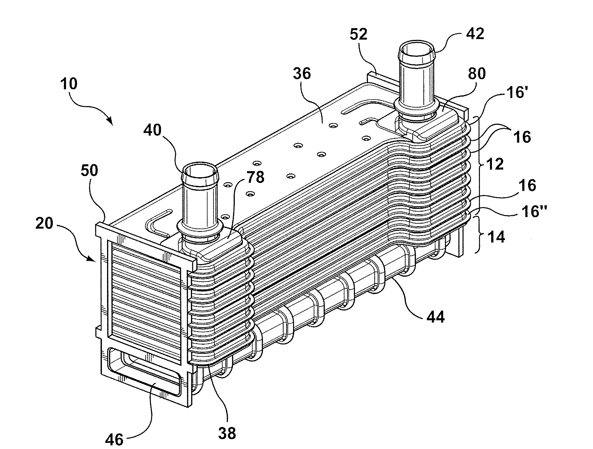
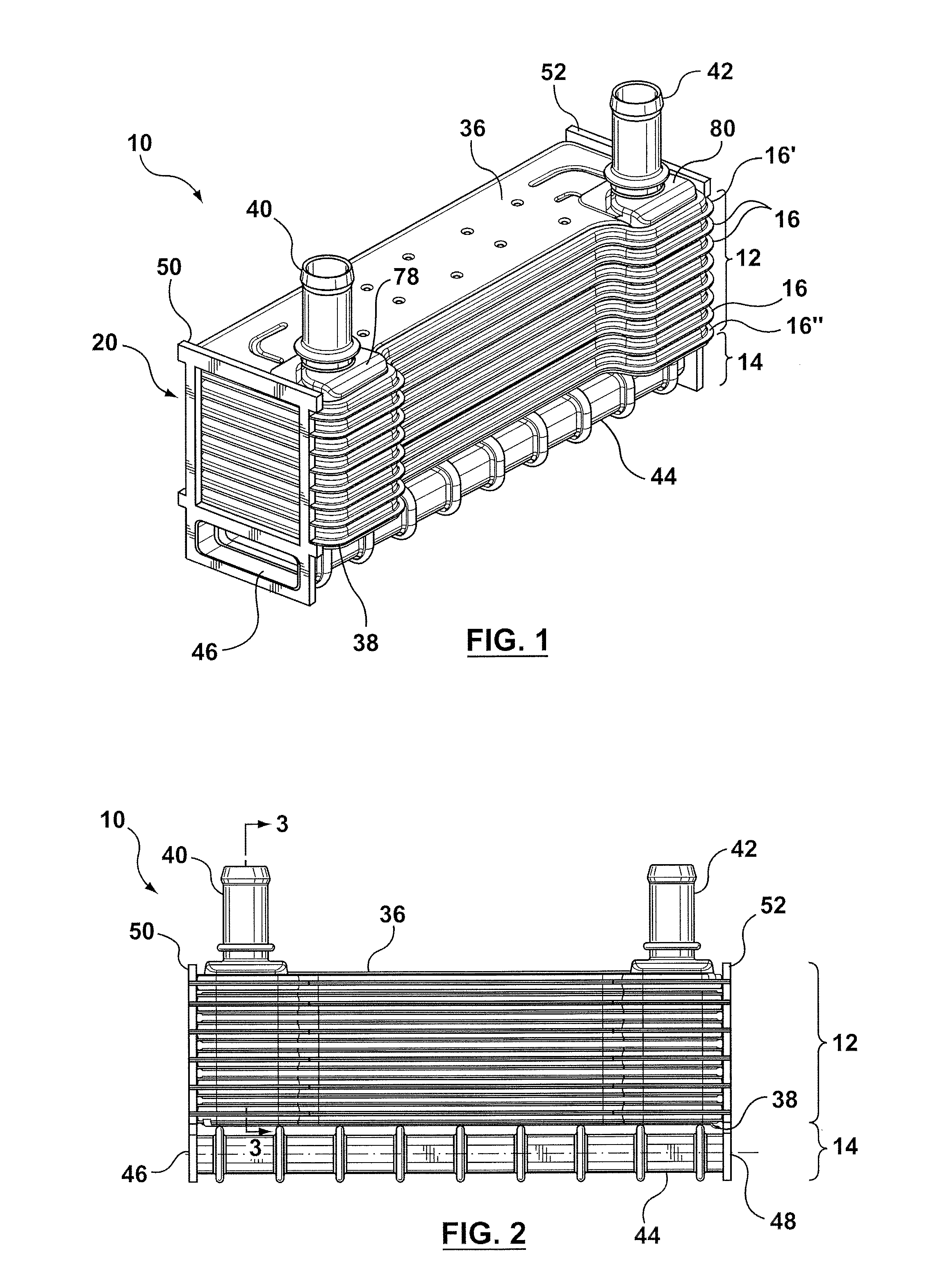
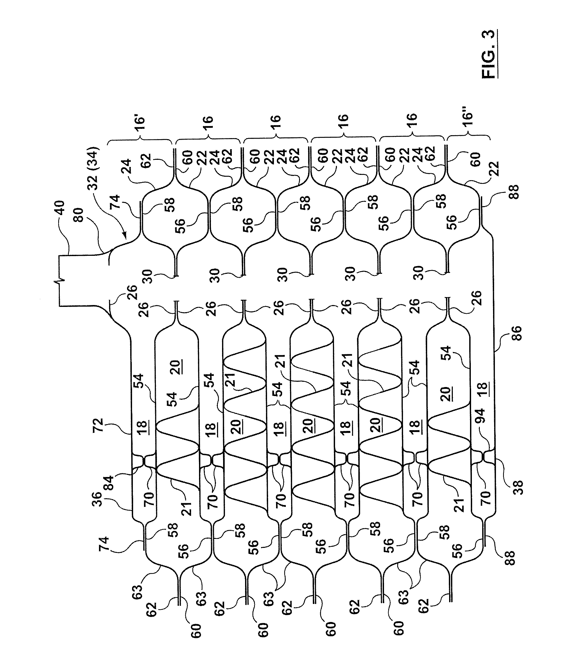
[0025]Referring to the drawings, there is shown in FIG. 1 a heat exchanger 10 according to a preferred embodiment of the invention. Heat exchanger 10 is comprised of a core portion 12 and a bypass portion 14. The core portion 12 is formed by a plurality of stacked tubular members 16 which define a first set of flow passages 18 therethrough (see FIG. 3) for the flow of a first fluid, such as a coolant, through the heat exchanger 10. A second set of flow passages 20 is defined between adjacent tubular members 16 for the flow of a second fluid, such as exhaust gas, through the heat exchanger 10. Turbulizers 21 may be located in the second set of flow passages 20 to increase heat exchange. While tubular members 16 may be formed by a single tubular element, they may also be formed of upper and lower plates 22, 24 and, therefore, may also be referred to as plate pairs. The tubular members 16 (or plate pairs) have boss portions 26, 28 (see FIG. 4), one at each end of the tubular members 16...


PUM


Abstract

A heat exchanger with an external bypass is formed by a core portion including a plurality of stacked tubular members and a corrugated bypass tube positioned substantially parallel to the core portion. A first set of flow passages is defined within the tubular members for the flow of a first fluid therethrough, and a second set of flow passages is defined between adjacent tubular members as the tubular members are stacked together to form the core portion. A pair of external end plates is sealingly attached to transverse end wall portions of the stacked tubular members and to the ends of the bypass tube thereby forming the heat exchanger with an external bypass that comprises a single unit that can be brazed or joined together in a single operation.

Description

FIELD OF THE INVENTION[0001]The invention relates to heat exchangers, and in particular, to heat exchangers with an integrated by-pass tube.BACKGROUND OF THE INVENTION[0002]Motor vehicles with internal combustion engines are sometimes equipped with an exhaust gas cooler or element in the exhaust system of the vehicle to permit cooling and / or recirculation of exhaust gas under certain operating conditions. The exhaust element has an inlet for receiving exhaust gas from the engine and an outlet for the exhaust gas to be recirculated back to the engine air intake or to other components in the exhaust line. Typically, the exhaust element includes an exhaust pipe extending between the inlet and outlet of the exhaust element, and a heat exchanger mounted generally in parallel with the exhaust pipe between the inlet and outlet of the exhaust element. Regulating or flow diversion means in communication with the inlet or outlet of the exhaust element directs the flow of the exhaust gas throu...

Claims


Application Information

Patent Timeline
Patent Type & Authority Applications(United States)
IPC IPC(8): F28F27/02
CPCF02M25/0728F02M25/0737F28D9/0043Y02T10/121F28D21/0003F28F9/0219F28F2250/06F28D9/0056F28F2250/108F02M26/25F02M26/32
Inventor PALANCHON, HERVE
Owner DANA CANADA CORP
Why Eureka
Try Eureka