Folding disk with wing stabilizer wheels

a technology of stabilizer wheels and folding disks, which is applied in the field of multi-section agricultural implements, can solve the problems of increasing the depth control problem of the corner with the wing size, difficult to maintain the outer corner of the wing-folding disk, and difficulty in reducing the wing thickness, so as to reduce the complexity of the system, improve the wing performance, and reduce the deflection of the outer wing frame members

Inactive Publication Date: 2008-05-15
DEERE & CO
View PDF24 Cites 16 Cited by
  • Summary
  • Abstract
  • Description
  • Claims
  • Application Information

AI Technical Summary

Benefits of technology

[0007]In one embodiment of the invention, the front gauge wheels are hydraulically controlled by a control valve on the tractor. Independent control allows the operator to make on-the-go depth control adjustments at the front of the disk depending on field conditions. In another embodiment, the front gauge wheels can be tied mechanically to the primary wing depth control wheels by an adjustable link such as a turnbuckle to decrease system complexity.
[0008]During operation, the front stabilizer wheels help control the forces on the outer wing gang to prevent wing gouging problems commonly experienced on most other free-floating disk wings. The adjustable on-the-go stabilizer wheels improve wing performance significantly compared to disks that rely on the wing depth control wheels to prevent gouging. The stabilizer wheels are located adjacent the front gang and can follow ground contour changes before the wing disk blades encounter the changes.
[0009]Frame deflection in the outer wing frame members is reduced compared to manually adjusted front stabilizer wheels since both the front stabilizer wheels and rear wheels provide support. With the support of the front stabilizer wheels during field transport, the position of the wing depth control wheels can be positioned near the rear of the frame so that very expensive heavy frames are no longer required. Wing weight is shared by the front gauge wheels and rear wheels during field transport for more balanced wheel loading. Additional rear weight of rear attachments such as a coil tine harrow that shifts weight balance to the rear of the disk is more effectively supported by the new wheel arrangement. The wheel arrangement also permits the disk size to be increased without compromising depth control performance. The gauge wheel concept can also be used with narrower three-section frames to enhance implement performance.

Problems solved by technology

Depth control on the front, outer corner of wing-folding disks is difficult to maintain because of the forces acting on the disk blades at the corner.
Reliance on the primary wing lift wheel assemblies is often ineffective since the wheels are located behind the front gang and ground contour changes will have already passed the front gangs before being encountered by the wheels.
Also, with the wings unfolded the corner wheels fail to provide support for the frame during field transport, and the rear wheels have to support the wing weight during transport.
The corner depth control problems increase with wing size.
As a result, as disks are made larger, there are more limitations on optimum performance than with narrower width disks.
This problem is common with three- or four-section disks that have one set of folding wings, as well as five-section disks having two sets of folding wings.

Method used


Image

  • Folding disk with wing stabilizer wheels
  • Folding disk with wing stabilizer wheels
  • Folding disk with wing stabilizer wheels

Examples


Embodiment Construction

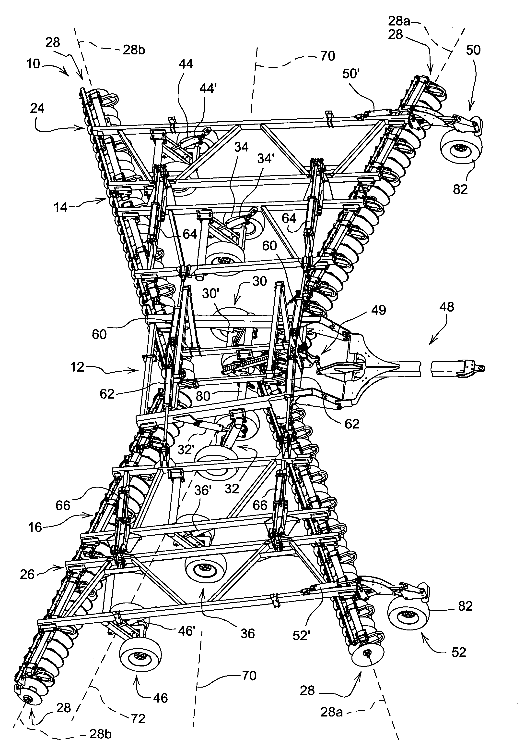
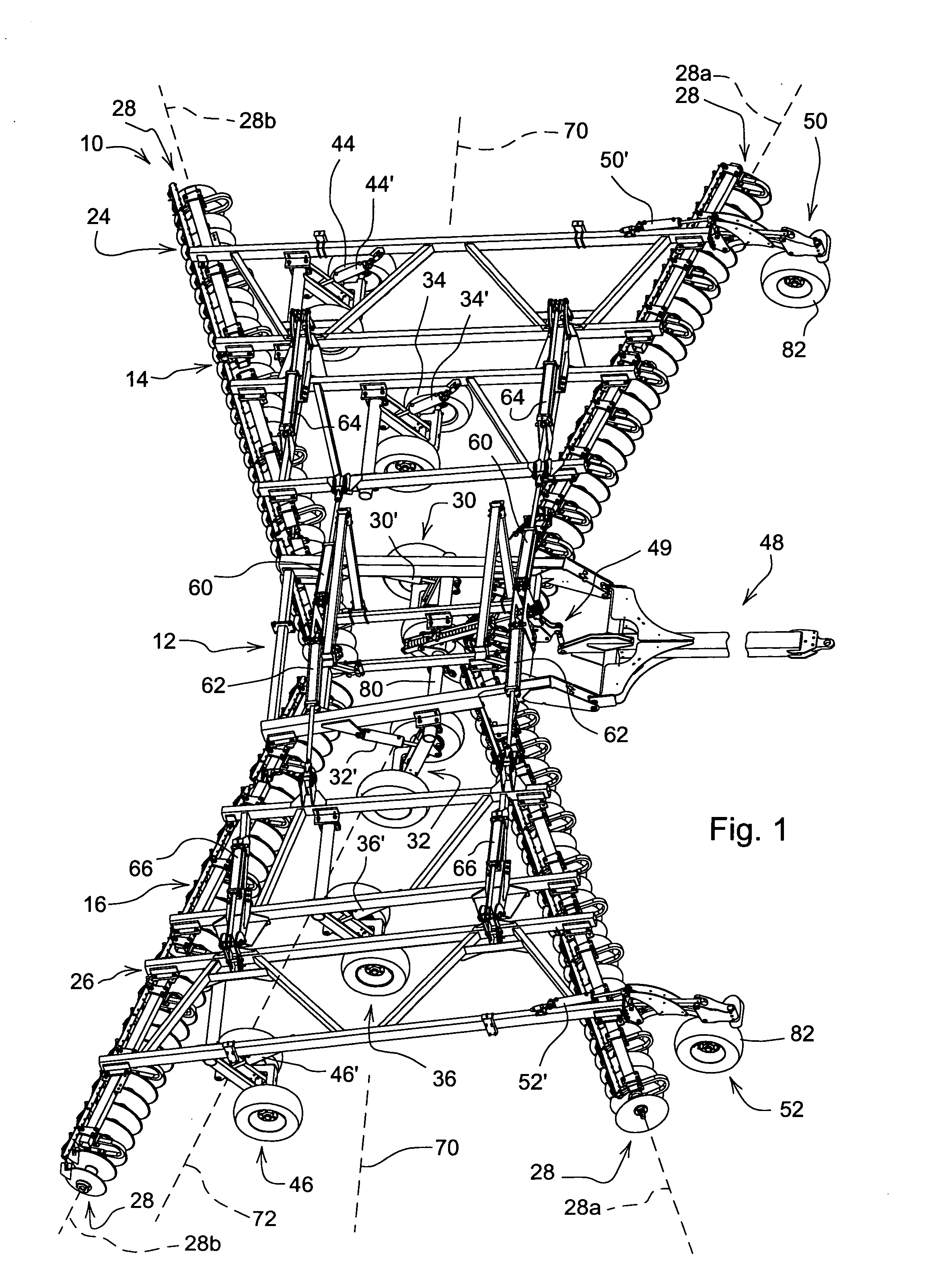
[0012]Referring now to FIG. 1, an agricultural implement such as a disk 10 includes a center main frame 12, left and right inner or primary wing frames 14 and 16, and outer wing frames 24 and 26 supporting forward and rearward angled gangs of earthworking tools such as disk blade assemblies 28. The main frame 12 is supported by lift wheel assemblies 30 and 32. The inner wing frames 14 and 16 are hinged from the main frame 12 and include lift wheel assemblies 34 and 36. The outer wing frames 24 and 26 are hinged to the outermost portions of the inner wing frames 14 and 16 and include lift wheel assemblies 44 and 46. A forward leveling hitch 48 connected at an aft end to the center main frame 12 is adapted for connection to a tractor (not shown) for forward movement over the ground. A leveling linkage 49 is connected between the hitch 48 and the lift wheel assemblies 30 and 32 to control disk attitude as the disk 10 is raised and lowered. The hinged frame connections and wheel assembl...


PUM


Abstract

Gauge or stabilizer wheels are located at the outer front portions of disk wing frames and are connected for operation with other disk wheels on the main and wing frames. The front stabilizer wheels bear much of the wing loading and allow the wing primary depth control wheels to be positioned further to the rear of the machine. The front stabilizer wheels can be hydraulically controlled for on-the-go forward depth control adjustments and provide frame support when the disk is in a field transport position.

Description

FIELD OF THE INVENTION[0001]The present invention relates generally to multi-section agricultural implements and more specifically to folding disks.BACKGROUND OF THE INVENTION[0002]Depth control on the front, outer corner of wing-folding disks is difficult to maintain because of the forces acting on the disk blades at the corner. The combination of side thrust forces along the axis of the disk gang and draft forces perpendicular to the axis of the gang results in the outer disk blades trying to go deeper while the blades on the opposite end of the gang react by rising to shallower depths. Reliance on the primary wing lift wheel assemblies is often ineffective since the wheels are located behind the front gang and ground contour changes will have already passed the front gangs before being encountered by the wheels.[0003]Several approaches exist to counter the negative effects of the side and draft forces. One approach is a rigid frame structure to minimize deflection with depth cont...

Claims


Application Information

Patent Timeline
Patent Type & Authority Applications(United States)
IPC IPC(8): A01B63/14
CPCA01B63/22
Inventor CONNELL, RICHARD JOSEPHBIERL, JAMES FRANKLIN
Owner DEERE & CO
Why Eureka
Try Eureka