Eureka AIR delivers breakthrough ideas for toughest innovation challenges, trusted by R&D personnel around the world.

Systems and methods for interference cancellation

a technology of interference cancellation and interference, applied in the field of signal processing, can solve the problems of loss of signal dynamic range, fixed notch filter, inability to adapt to new interferers, etc., and achieve the effects of reducing system complexity, cost, weight, and power

Inactive Publication Date: 2010-06-24
L 3 COMM INTEGRATED SYST
View PDF32 Cites 43 Cited by
  • Summary
  • Abstract
  • Description
  • Claims
  • Application Information

AI Technical Summary

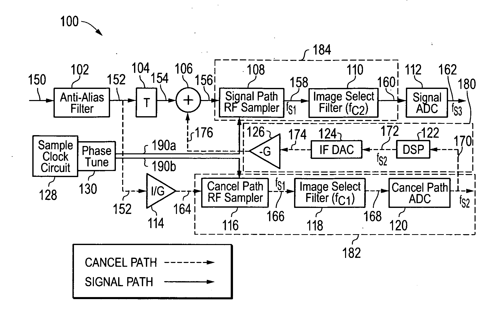
Benefits of technology

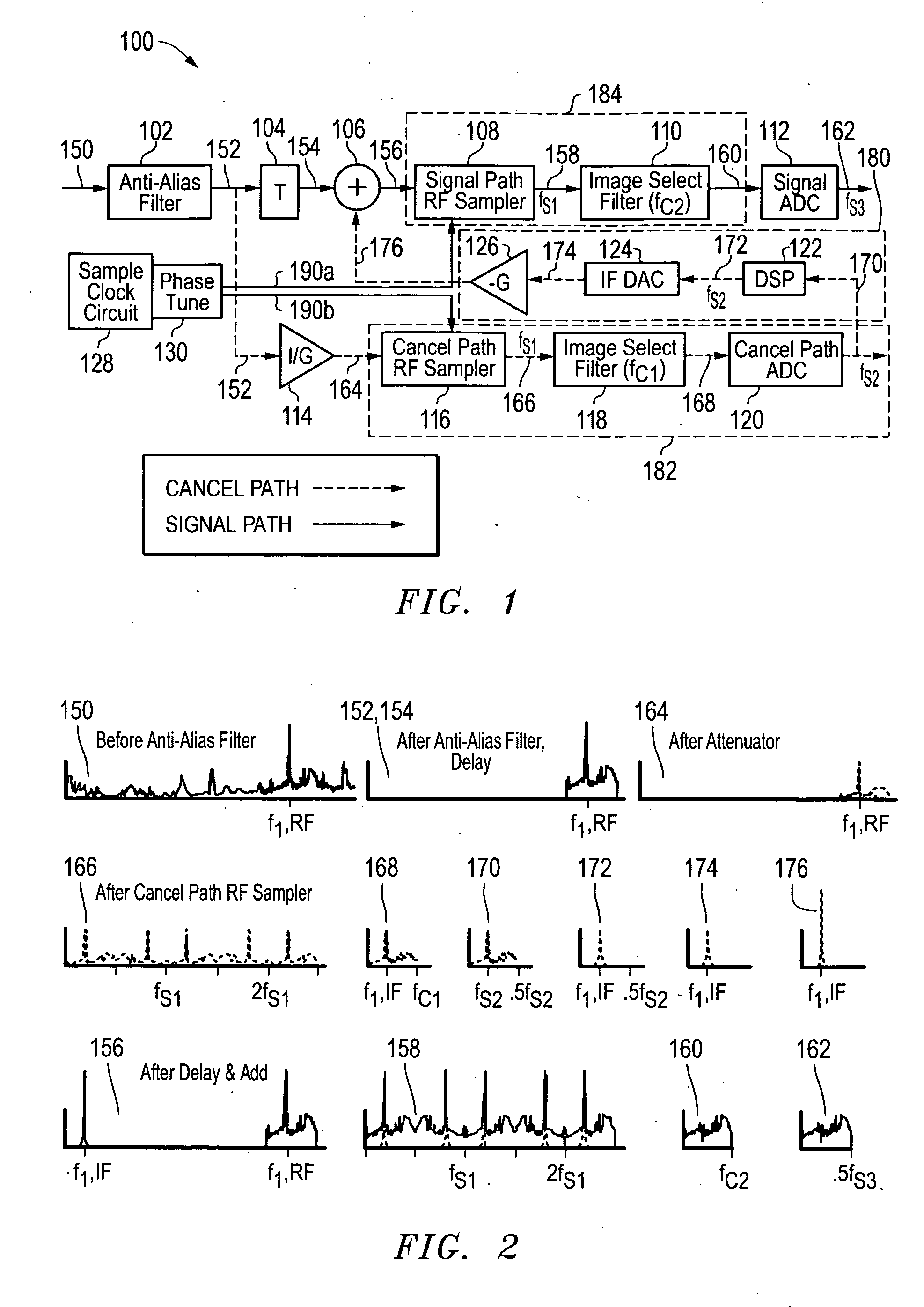
[0011]Since the disclosed systems and methods may be implemented without up-conversion of the cancellation signal, errors introduced by the up-conversion process may be avoided, e.g., including phase noise and mis-match between desired frequency / phase and achieved mixer frequency / phase. Further, the disclosed systems and methods may be implemented without knowledge of the exact frequency of the signal to be cancelled. Note that when up-converting the cancellation signal, any frequency estimation error can result in not just imperfect cancellation, but can even introduce an extra interferer (namely the cancellation signal itself). This embodiment provides the particular advantage that the system complexity may be greatly reduced while maintaining good performance, thus the cost, size, weight, and power may all be significantly reduced when compared to approaches relying on conventional technology.
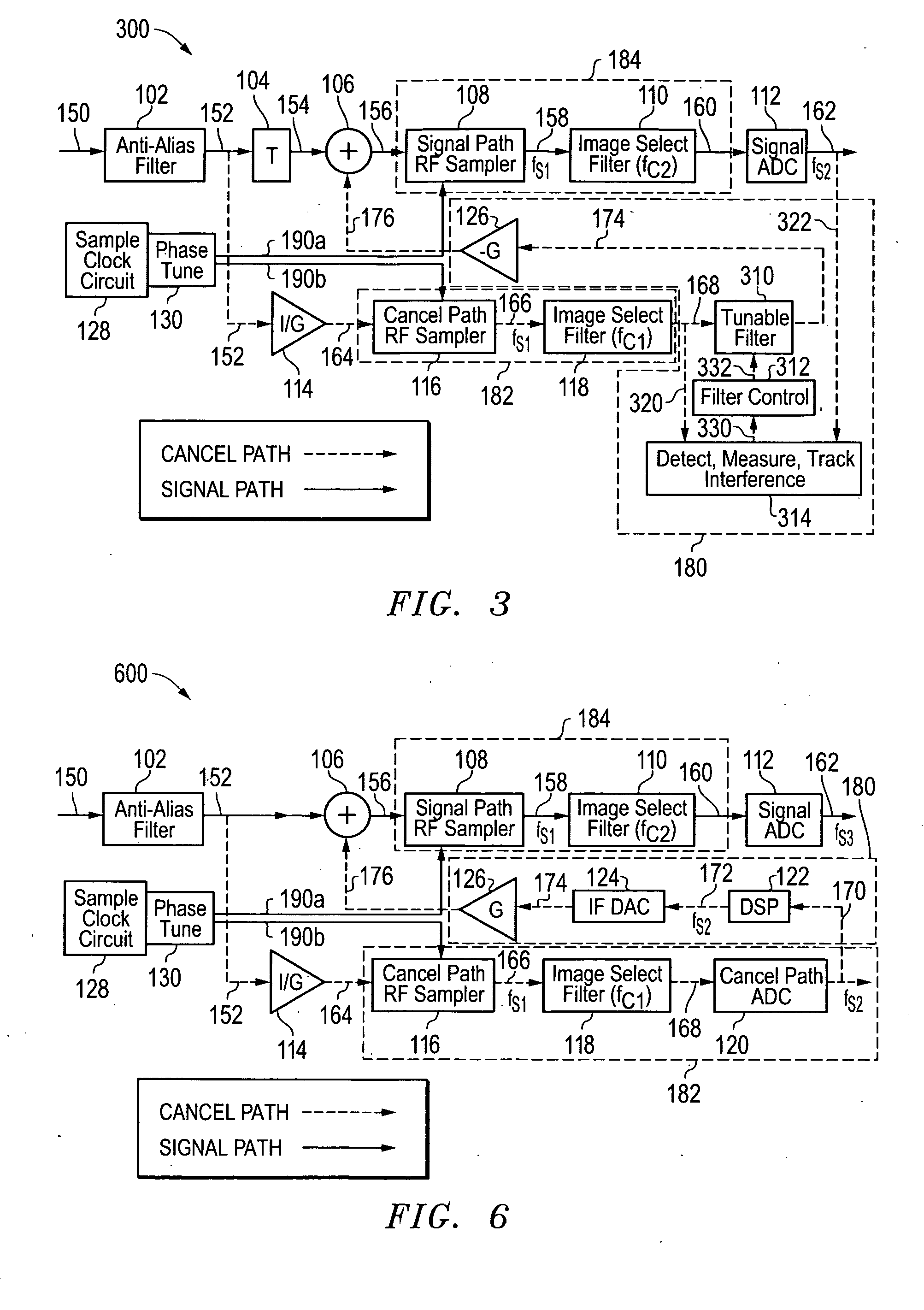
[0012]In one exemplary embodiment of the disclosed systems and methods, the impact of sample clock imperfections may be mitigated by using the same clock for both the signal and cancel paths. In this regard, the same clock may be employed to drive two system pulse-based samplers (i.e., a signal path sampler and a cancellation path sampler) so that the folded IF signal is synchronized with the RF signal to meet the condition of canceling the RF signal at the sample instances. In another embodiment, a cancellation signal may be synchronized with the RF signal, for example, by developing the cancellation signal using a bandpass sampling ADC in the cancel path. In yet another exemplary embodiment, the disclosed systems and methods may be implemented in conjunction with a Nyquist folding receiver.
[0013]In one exemplary embodiment, an interference cancellation system may be provided for cancellation of narrow band periodic interferers that utilizes two RF samplers and two interpolation filters, with a first RF sampler and a first interpolation filter coupled in series within a signal path of the interference cancellation system, and with a second RF sampler and a second interpolation filter coupled in series within a cancel path of the interference cancellation system. The signal path and cancel path of the interface cancellation system may be fed with an analog input RF signal. The IF output of the second interpolation filter of the cancel path may be fed back to the input of the first RF sampler of the signal path for cancellation after being delayed by a tunable time delay. The folded frequency that is canceled depends on the time delay, which may be tuned to control the frequency of the folded cancelled signal, e.g., to achieve phase cancellation (rather than signal inversion) so that the cancel path signal is 180 degrees out of phase with the signal path signal and so that cancellation is phase dependent. All RF signals which fold to the same IF are cancelled, which in effect generates a series of notches throughout the spectrum, allowing cancellation of an RF interferer with an IF signal without the need to estimate the Nyquist zone. Although the cancellation may have a few other partial nulls, the majority of the band is still receivable and the average clock rate may be changed to cause the partial nulls and the nulls in other Nyquist zones to move, without having to know which Nyquist zone the RF interferer is from that is being cancelled.
[0014]In one exemplary embodiment, the disclosed systems and methods may be employed with changing clock rate, and the ability to track cancellation as RF sample rate changes may be provided by monitoring the interference power level and adapting the time delay (e.g., using adaptive time delay circuitry) in a power minimization scheme (e.g., such as constrained power minimization). The ability to so track cancellation as RF sample rate changes may be enhanced when the RF sample rate changes smoothly.

Problems solved by technology

Loss of signal dynamic range is a problem commonly caused by strong interferers in a radio frequency (RF) environment.
Fixed notch filters can handle known RF interferers, but cannot adapt to new interferers.
Tunable notch filters, while providing more flexibility, suffer from lack of tuning resolution.
Attempts at developing tunable notch filters with adequate Q has been an active area of research for years and continues to be a significant technical challenge.
However, even if tunable notch filters could meet the desired Q requirements, they still lack flexibility in that they can only cancel a single interferer per notch.
However, these techniques do not apply to frequency cancellation and do not apply to single channel receivers in any case.
Furthermore, even spatial beamformers may be susceptible to dynamic range issues caused by strong interferers.

Method used


Image

  • Systems and methods for interference cancellation
  • Systems and methods for interference cancellation
  • Systems and methods for interference cancellation

Examples


Embodiment Construction

[0031]FIG. 1 illustrates a direct RF interference cancellation (DRIC) system 100 as it may be configured according to one embodiment of the disclosed systems and methods. As shown in FIG. 1, system 100 is configured to receive an analog input radio frequency (RF) signal 150 (e.g., from a RF antenna or other suitable source) and to provide a digital selected sample signal 162. Analog input RF signal 150 may include one or more desired signals in the presence of one or more interferer signals. In one embodiment, a DRIC system 100 may be employed to provide interference cancellation for a reconfigurable direct RF receiver to allow significantly improved dynamic range over conventional methods. Examples of such reconfigurable direct RF receivers include those receiver systems described in U.S. patent application Ser. No. 11 / 247,338 entitled “RECONFIGURABLE DIRECT RF BANDPASS SAMPLING RECEIVER AND RELATED METHODS,” filed on Oct. 11, 2005; and U.S. Pat. No. 7,436,910 entitled “DIRECT BAND...


PUM


Abstract

Systems and methods for interference cancellation in which a first signal having a first frequency may be cancelled with a second frequency having a second and different (e.g., lower) frequency by employing sampling to cancel the first signal with the separate signal at the sample instances.

Description

[0001]This application is related in subject matter to concurrently filed U.S. patent application Ser. No. ______ (Attorney Docket LCOM-083), entitled “INTERFERENCE CANCELLATION FOR RECONFIGURABLE DIRECT RF BANDPASS SAMPLING INTERFERENCE CANCELLATION” by Fudge, which is hereby incorporated by reference in its entirety.FIELD OF THE INVENTION[0002]This invention relates generally to signal processing, and more particularly to interference cancellation.BACKGROUND OF THE INVENTION[0003]Loss of signal dynamic range is a problem commonly caused by strong interferers in a radio frequency (RF) environment. Typical approaches employed to address strong interferers include the use of fixed or tunable notch filters. Fixed notch filters can handle known RF interferers, but cannot adapt to new interferers. Systems employing fixed notch filters must be re-designed and modified substantially if the fixed interference environment changes. Tunable notch filters, while providing more flexibility, suf...

Claims


Application Information

Patent Timeline
Patent Type & Authority Applications(United States)
IPC IPC(8): H04B1/10
CPCH04B1/1036
Inventor FUDGE, GERALD L.BLAND, ROSS E.KUSMANOFF, ANTONE L.
Owner L 3 COMM INTEGRATED SYST
Why Eureka
Eureka Blog
Learn More