Optical transceiver module with power integrated circuit

a technology of integrated circuits and optical transceivers, applied in the field of fiber optic transceivers, can solve the problems of significant increase in circuitry complexity, occupying valuable space on the circuit board of resistors and/or thermistors, and significantly reducing circuitry complexity, so as to reduce circuitry complexity, less circuit board space, and simple operation

Inactive Publication Date: 2008-04-15
II VI DELAWARE INC
View PDF6 Cites 44 Cited by
  • Summary
  • Abstract
  • Description
  • Claims
  • Application Information

AI Technical Summary

Benefits of technology

[0018]Consequently, the above described transceiver module includes a single, shared internal serial bus that connects to numerous components in the transceiver module. This allows a plurality of functions to be performed via a single electrical connection to each component. Also, overall system complexity is reduced by eliminating the need for multiple analog or digital lines to each component. This conserves valuable board area for other components or circuitry and may even allow for a more compact transceiver module. In addition, the internal serial bus allows for scalability. For example, new integrated circuits (ICs) may be coupled to the internal serial bus, thereby sharing input and output ports on the main controller. These input and output ports are generally used for sending setup commands to the ICs or receiving monitoring information from the ICs. In addition, new ICs having additional functionality or features may be swapped with existing ICs without requiring any additional input and output ports, i.e., adding functionality with little circuit redesign.
[0019]Moreover, the above described transceiver module provides more complete and accurate control and monitoring of the transceiver module's parameters.
[0023]In this way, a single power controller IC is used to supply power to the various components within the optical transceiver. This power controller IC is simple to operate and clearly reduces circuitry complexity by providing a centralized source of power. Furthermore, a single power controller IC requires significantly less circuit board space than prior power sources. In addition, such power sources are adjustable, i.e., the main controller can set the voltages and / or shutdown the regulators, if necessary. This adjustability may be used to compensate for component degradation over time. In other words, as a component degrades over time its voltage requirements may increase. Moreover, such adjustability provides for the power requirements of future optical transceivers without requiring a complete redesign of the power supply. Such adjustability also makes such an optical transceiver more scalable. Finally, the power controller IC provides for more precise temperature control and compensation.

Problems solved by technology

Setup of these components generally occurs each time the optical transceiver is powered-up, as the individual components generally have volatile memories that lose setup data when powered-down.
In addition, such resistors and / or thermistors take up valuable space on the circuit board 102.
Moreover, each time additional features are added to the optical transceiver, the complexity of the circuitry increases significantly.
For example, in use, as many as twelve connections may be needed to the transmitter circuit, thereby significantly increasing circuitry complexity.
Still further, such prior art systems are generally not scalable, i.e., they cannot easily be expanded to allow additional functionality.
However, these analog signals lines do not address many of the drawbacks of the abovementioned prior art.
For example, a high number of inputs and outputs are still required, which leads to complex circuitry that takes up a significant amount of space on the circuit board 102.
These optical transceivers are still not scalable.
However, optical transceivers employing dedicated digital connections do not fully address the abovementioned drawbacks.
For example, the circuitry is still highly complex, especially for multiple inputs / outputs.
This circuitry, as in other prior art optical transceivers, takes up valuable circuit board space.
Such power sources take up valuable space and add further expense to the overall optical transceiver system.
Also, these power sources are typically fixed and not adjustable by the optical transceiver module itself.

Method used


Image

  • Optical transceiver module with power integrated circuit
  • Optical transceiver module with power integrated circuit
  • Optical transceiver module with power integrated circuit

Examples


Embodiment Construction

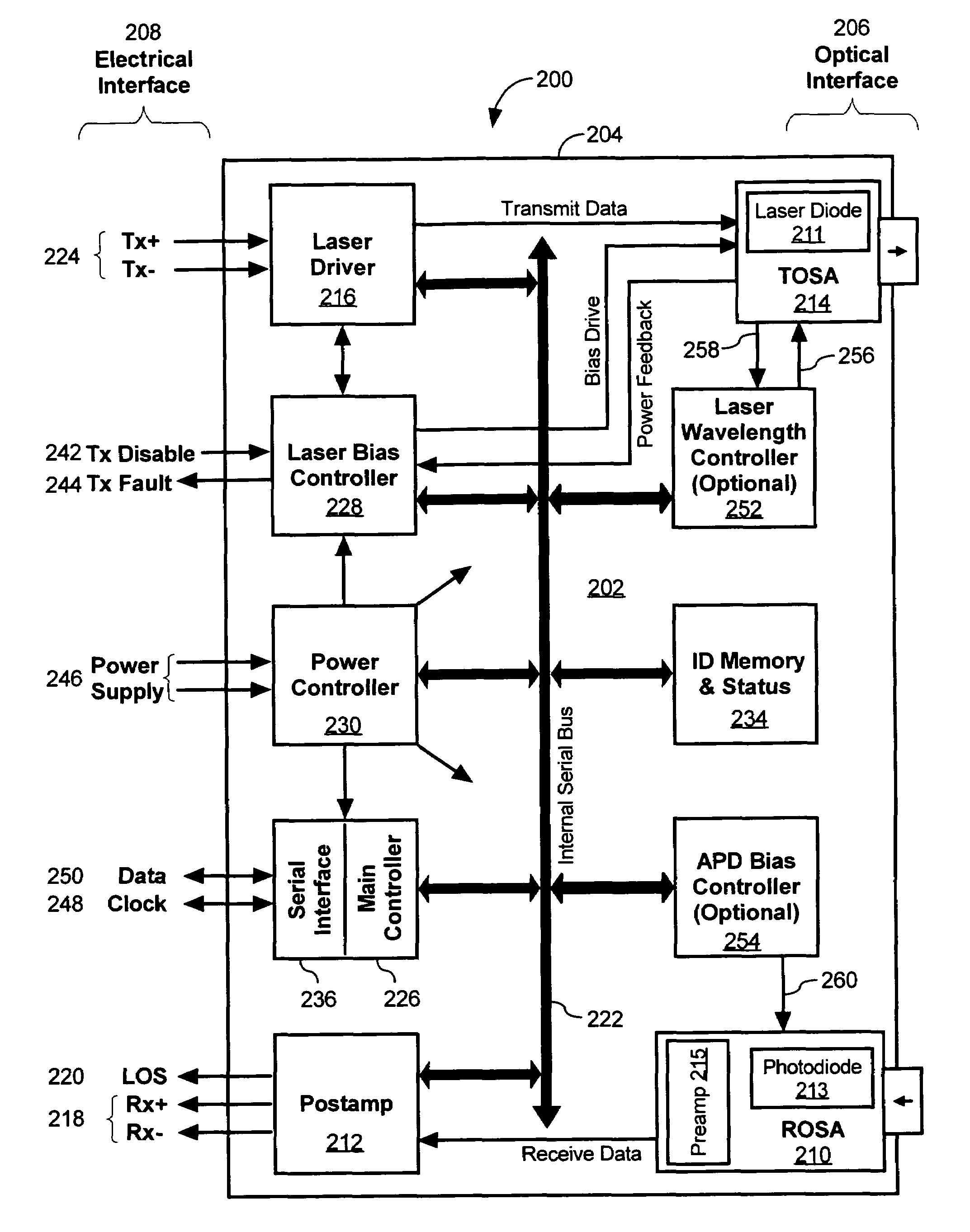
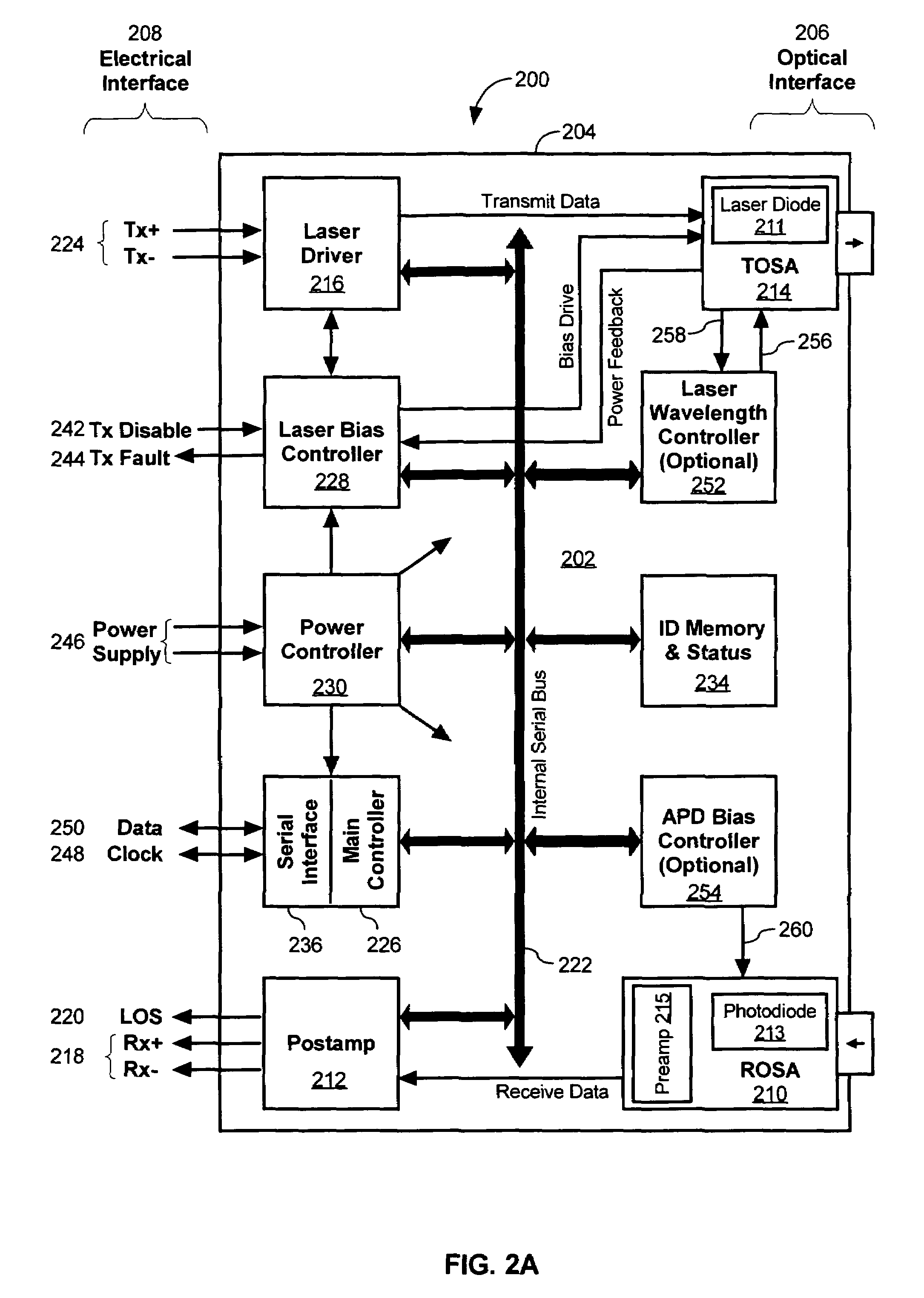
[0033]The present invention utilizes a shared internal serial bus to communicate with multiple addressable components in an optical transceiver module. As will be shown, the shared serial bus simplifies overall transceiver setup, control, monitoring, and safety functions, while reducing system complexity, freeing-up valuable board space, and allowing for scalability. In a preferred embodiment, the serial bus monitors: laser bias current from the laser bias controller; laser output power; received average power; received modulated power; APD bias voltage; temperature; current in a thermoelectric cooler (TEC) controller; temperature in the TEC controller; wavelength; error rates; signal integrity; or the like.

[0034]FIG. 2A is a schematic representation of the circuitry and components of an optical transceiver module that uses a component address serial protocol, according to an embodiment of the invention. The transceiver module 200 preferably includes at least one circuit board 202 h...


PUM


Abstract

The optical transceiver module includes a housing and a plurality of components disposed at least partially within the housing. The components include an optical transmitter, an optical receiver, and a power controller integrated circuit (IC). The power controller IC is electrically coupled to at least one of the plurality of components. The power controller IC is configured to perform power supply functions for the optical transceiver module. Also, the power controller IC includes multiple voltage regulators providing power to the components at two or more voltages.

Description

[0001]This patent application is a Continuation-In-Part application of patent application Ser. No. 09 / 777,917, filed Feb. 5, 2001 now U.S. Pat. No. 7,079,775, and of patent application Ser. No. 10 / 266,870, filed Oct. 8, 2002, now U.S. Pat. No. 6,912,361 both of which are hereby incorporated by reference.BACKGROUND OF THE INVENTION[0002]1. Field of the Invention[0003]The present invention relates generally to the field of fiber optic transceivers and particularly to an optical transceiver having an internal power controller integrated circuit (IC) for regulating and supplying power to the various components within the optical transceiver module.[0004]2. Description of Related Art[0005]Fiber optic transceivers, otherwise know as optoelectronic transceivers, transmit and receive both light and electronics signals, i.e., they provide for the bi-directional communication of signals between an electrical interface and an optical interface.[0006]FIG. 1 is a schematic representation of the ...

Claims


Application Information

Patent Timeline
Patent Type & Authority Patents(United States)
IPC IPC(8): H04B10/00H04BH04B10/02H04B10/08H04B10/43
CPCG02B6/4246H04B10/0799H04B10/40G02B6/4284G02B6/42
Inventor ARONSON, LEWIS B.LIGHT, GRETA L.HOSKING, STEPHEN G.
Owner II VI DELAWARE INC
Why Eureka
Try Eureka