
Predistortion with integral crest-factor reduction and reduced observation bandwidth

a crest factor and predistortion technology, applied in the field of radio frequency signal amplification, can solve the problems of interference in adjacent channels, unsatisfactory interference, and violation of transmitter licensing and regulatory spectral emission requirements, and achieve the effect of reducing processing requirements and reducing observation bandwidth

Active Publication Date: 2013-05-21
MAXLINEAR ASIA SINGAPORE PTE LTD
View PDF13 Cites 50 Cited by
  • Summary
  • Abstract
  • Description
  • Claims
  • Application Information

AI Technical Summary

Benefits of technology

This patent invention is about improving the performance of predistortion linearization in wireless communication systems. It combines the previously separate operations of predistortion and crest factor reduction (CFR) into a single operation, which reduces processing requirements and simplifies the overall process. The technique also decreases the impact of out-of-band emissions and takes into account the dominant impairment of non-linear amplifiers in certain circumstances. Overall, this invention improves the performance of predistortion linearization while reducing system complexity.

Problems solved by technology

The products of the intermodulation can appear within the bandwidth of the input signal causing undesirable interference.
Such out-of-band products can cause interference in adjacent channels and violate transmitter licensing and regulatory spectral emission requirements.
Although filtering can be used to remove the unwanted out-of-band distortion, filtering is not always practical, especially if the amplifier is required to operate with multiple frequencies.
Intermodulation can also be a problem when multiple signals are amplified in the same amplifier even if they individually do not have amplitude variations.
Power amplifiers can introduce some distortion even when well designed.
Perfect linearity over a wide range of amplitude is impractical to realize in practice.
In addition, as any power amplifier nears its maximum output power capacity, the output no longer increases as the input increases.
However, with that type of operation, known as “backed off,” the power amplifier has a relatively low supplied power to transmitted power conversion efficiency.
For example, a “Class A” amplifier may be linear enough to transmit a signal cleanly, but may be only 1% efficient.
Low efficiency is wasteful of power and increases the size and cost of the power amplifier.
Further, the power that is wasted is dissipated as heat, which has to be removed by cooling.
However, as described earlier, high-power linear amplifiers are generally inefficient and undesirable in systems in which cost and heat dissipation are prohibitive factors, for example, cellular telephone basestations, wireless access points, and the like.
Analog feedback techniques have been reported, but these approaches can be limited to relatively narrow operating bandwidths, can be extremely sensitive to amplifier variations, and can be prone to instability.
Consequently, these designs may not be appropriate for mass production.
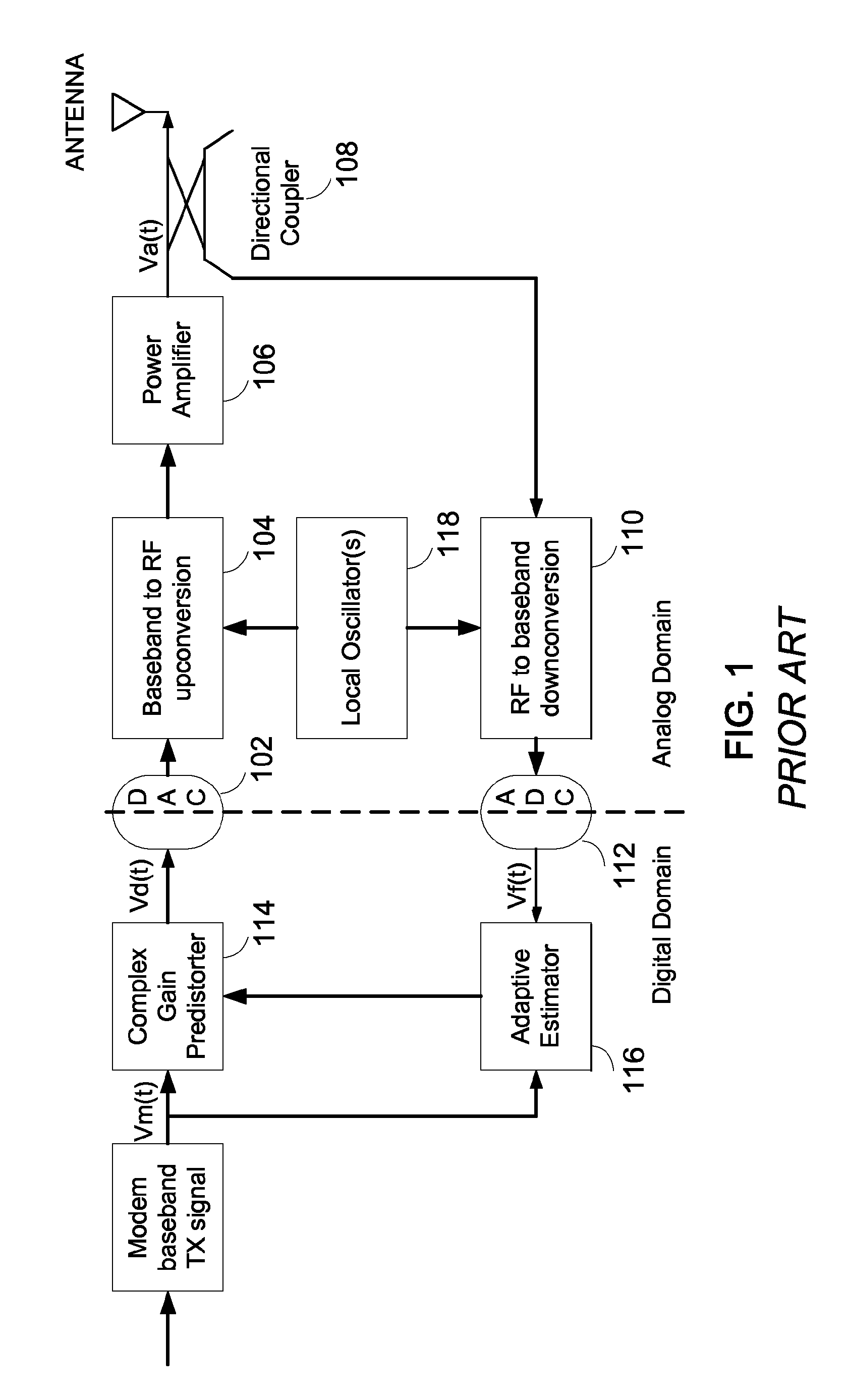
For example, those portions of the desired reference signal Vm(t) that exercise the saturated portion of the amplifier transfer characteristic (where its slope is approaching zero), cannot be effectively linearized due to the very large instantaneous corrective gain that would be applied by the predistorter 114.
The output power backoff (OPBO) technique is effective in reducing the amount of nonlinearity, but typically incurs a relatively large loss of amplifier efficiency due to amplifier operation below saturation.
Applying predistortion in that scenario can extend an amplifier's input range for a given level of acceptable distortion, but does not otherwise fundamentally improve upon the limitation posed by the maximum saturated output power of the amplifier.
Often, this crest factor reduction (CFR) is achieved at the expense of impairing in-band error vector magnitude (EVM), which can limit its application when EVM is subject to regulation.
One disadvantage of conventional CFR is the additional power and complexity of the CFR hardware, along with the processing latency incurred (for time-critical systems).

Method used


Image

  • Predistortion with integral crest-factor reduction and reduced observation bandwidth
  • Predistortion with integral crest-factor reduction and reduced observation bandwidth
  • Predistortion with integral crest-factor reduction and reduced observation bandwidth

Examples


Embodiment Construction

[0036]Although particular embodiments are described herein, other embodiments of the invention, including embodiments that do not provide all of the benefits and features set forth herein, will be apparent to those of ordinary skill in the art.

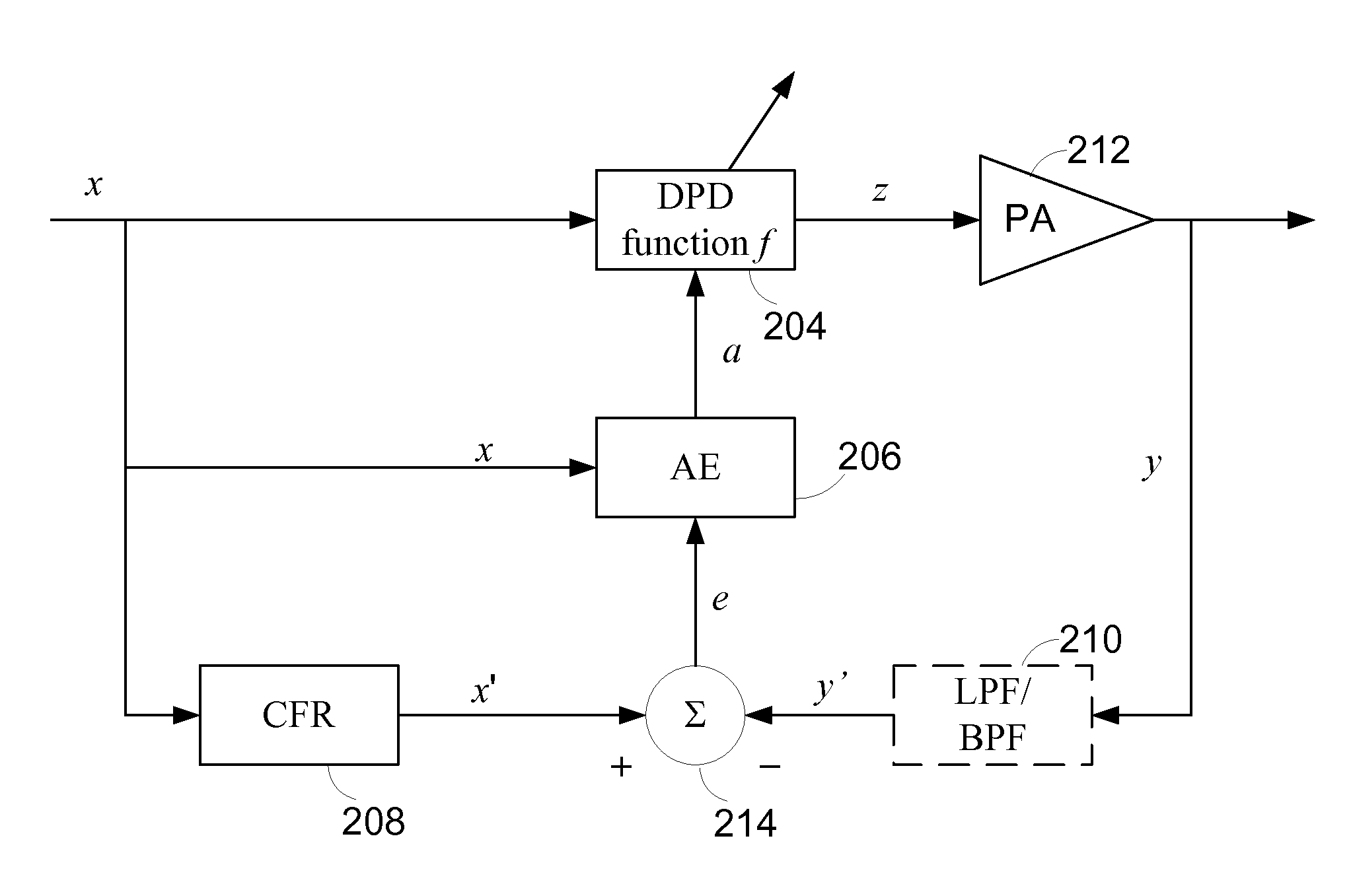
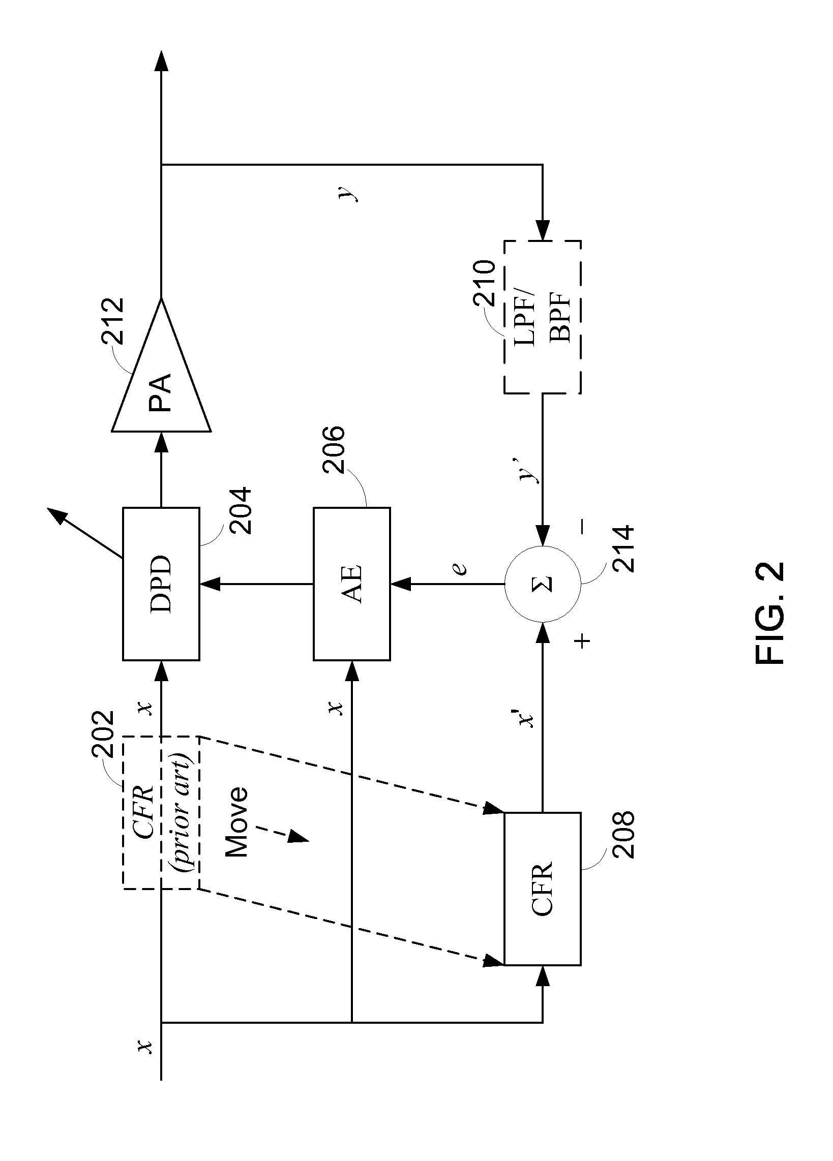
[0037]FIG. 2 contrasts an embodiment of the invention with a conventional crest factor reduction (CFR) technique. The block diagrams of FIGS. 2, 3, 5, and 6 are modeled at complex baseband so that blocks for quadrature modulation (when applicable), digital-to-analog conversion, upconversion, RF coupling, and downconversion, filtering for downconversion and anti-aliasing, analog-to-digital conversion, and quadrature demodulation are not shown. In conventional DPD systems with CFR, the CFR function is present in the signal path ahead of the predistorter (DPD) 204, as shown by the dashed box 202 of FIG. 2 or is present in both the forward signal path to the DPD 204 and in the forward signal path for the adaptive estimator AE 206. By contrast, in ...


PUM


Abstract

Apparatus and methods configure digital predistortion linearizers for power amplification of bandlimited signals using non-linear amplifiers. The predistorter is configured to achieve both crest factor reduction (CFR) and predistortion for linearization. One embodiment advantageously reduces processing requirements conventionally associated with CFR by considering only the in-band component, that is, the information bearing component, of the desired signal to be reproduced for those cases in which the mitigation of in-band error vector magnitude (EVM) is preferred over the reduction of spurious out-of-band emissions.

Description

BACKGROUND[0001]1. Field of the Invention[0002]Embodiments of the invention generally relate to radio frequency (RF) signal amplification, and in particular, embodiments relate to the amplification of multi-carrier signals.[0003]2. Description of the Related Art[0004]Radio frequency power amplifiers are widely used to transmit signals in communications systems. Typically, a signal to be transmitted is concentrated around a particular carrier frequency occupying a defined channel. Information can be sent as a modulation of amplitude, phase, frequency, or combination of these that causes the information to be represented by energy spread over a band of frequencies around the carrier frequency. In many schemes, the carrier itself is not sent since the carrier is not essential to the communication of the information.[0005]When a signal containing amplitude variations is amplified by a power amplifier, the amplified signal is distorted if the power amplifier does not exhibit a linear amp...

Claims


Application Information

Patent Timeline
IPC IPC(8): H04K1/02
CPCH04L27/368H03F1/3247H03F1/3258H03F3/245H03F3/195H04L27/2614H03F2201/3233H03F2200/204H03F2200/207H03F2201/3212
Inventor YEE, PAUL
Owner MAXLINEAR ASIA SINGAPORE PTE LTD
Learn More