Serial bus clock frequency calibration system and method thereof

a clock frequency and calibration system technology, applied in the direction of synchronising signal speed/phase control, generating/distributing signals, instruments, etc., can solve the problem of reducing the tolerable frequency error of 3.0, affecting the accuracy of clock frequency calibration, etc. problems, to achieve the effect of optimum clock frequency resolution

Active Publication Date: 2011-01-20
GENESYS LOGIC INC
View PDF7 Cites 44 Cited by
  • Summary
  • Abstract
  • Description
  • Claims
  • Application Information

AI Technical Summary

Benefits of technology

[0007]To eliminate the drawbacks of the aforementioned prior art, a primary objective of the present invention is to provide a serial bus clock frequency calibration system and a method thereof, which integrate two-stage clock frequency resolution calibrations with different frequency tuning ranges, one of which firstly treats the...

Problems solved by technology

However, under this manner, a super-speed signal transmission of USB 3.0 has a lower tolerable frequency error with relative to a high-speed or full-speed signal transmission of USB 2.0.
However, the usage of the external crystal oscillator 14 does not only cost higher but also invokes occurrence of a frequency error problem in the working frequency in comp...

Method used


Image

  • Serial bus clock frequency calibration system and method thereof
  • Serial bus clock frequency calibration system and method thereof
  • Serial bus clock frequency calibration system and method thereof

Examples


first embodiment

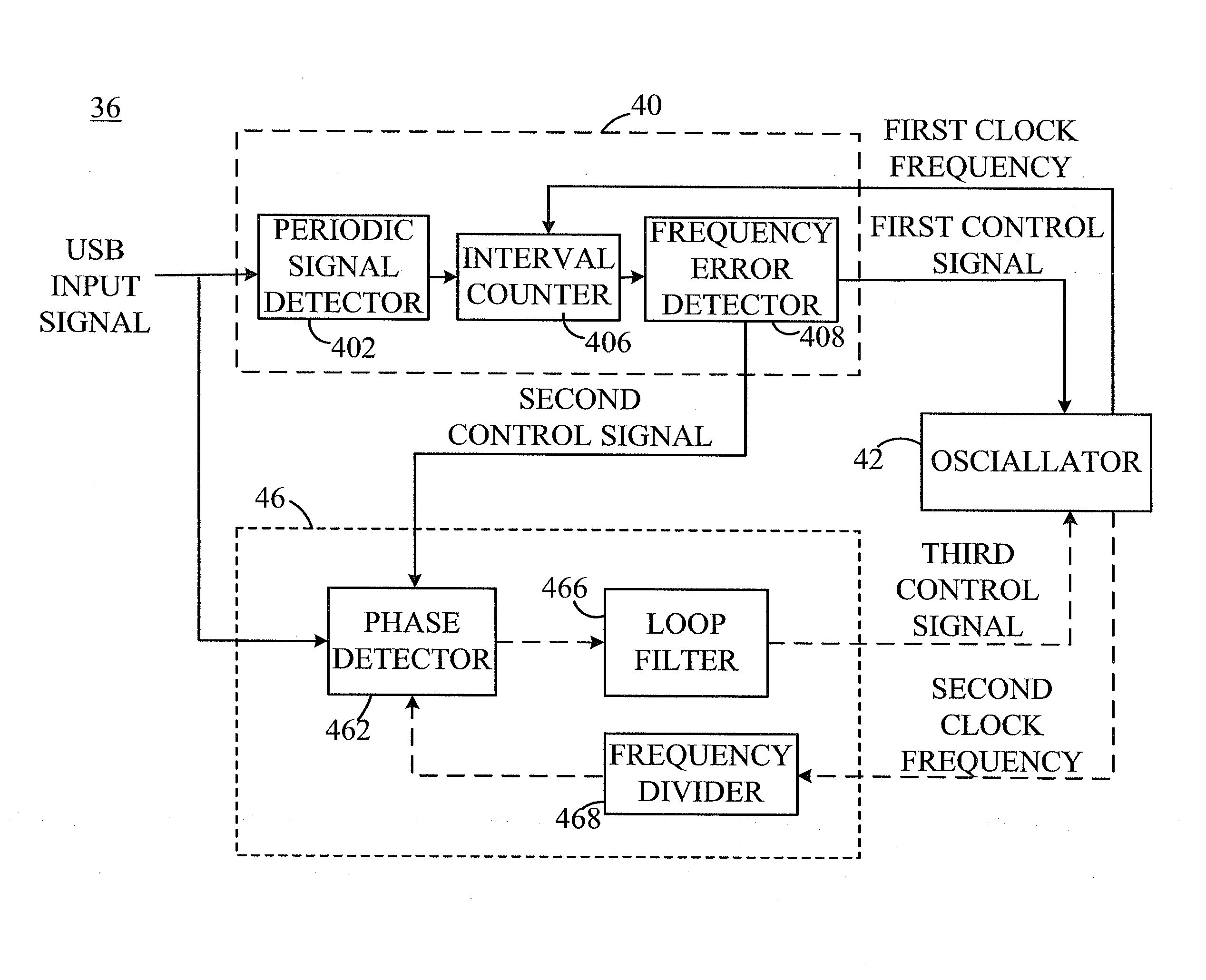
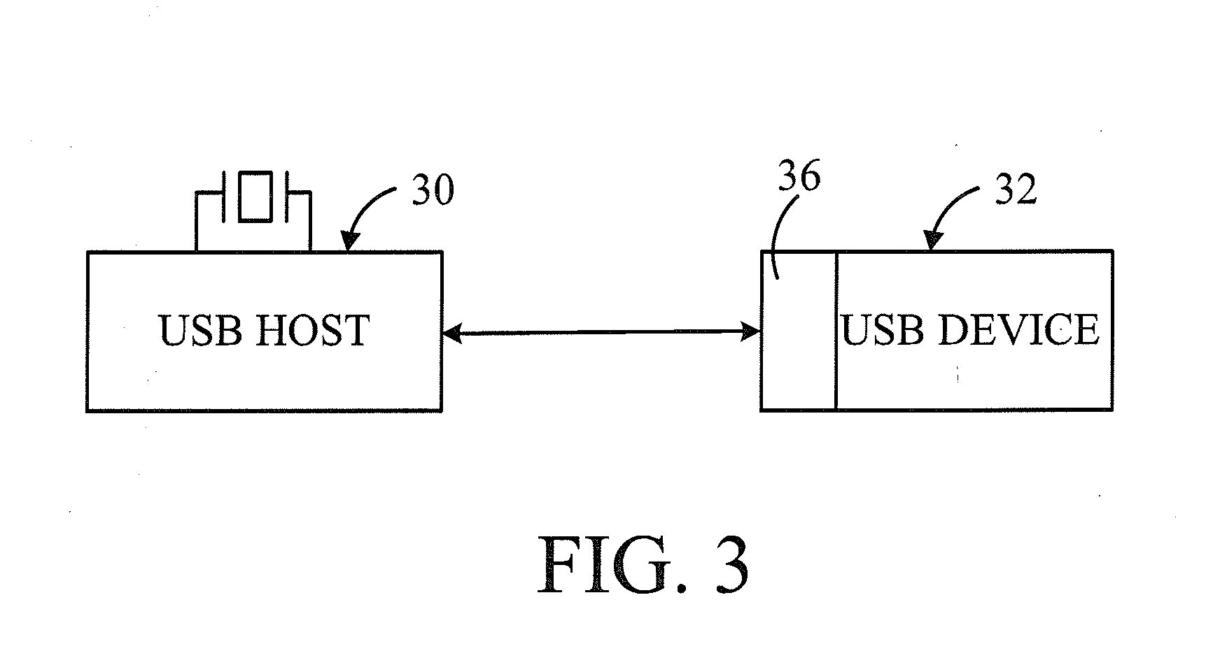
[0053]Referring to FIG. 3, a functional block diagram according to a first preferred embodiment of the present invention shows a USB (Universal Serial Bus) host 30 and a USB device 32 for performing a USB interface signal transmission there between. The USB device 32 such as a USB hub includes a serial bus clock frequency calibration system 36 configured to perform two-stage clock frequency resolution calibrations with different tuning ranges, according to a USB input signal transmitted from the USB host 30 to the USB device 32. The two-stage clock frequency resolution calibrations comprise a first-stage resolution calibration and a second stage resolution calibration. The first-stage resolution calibration utilizes a SOF signal of the USB input signal which is a periodic signal to be a preliminary reference for coarse tuning an operation clock frequency required for the USB device 32. By following the first-stage resolution calibration, the second stage resolution calibration utili...

third embodiment

[0077]In the third embodiment, when the link layer 74 determines the communication protocol mode between the USB host 30 and USB device 32 to be USB 2.0, the first frequency calibration device 40 is utilized by the link layer 74 to receive the first type serial bus input signal, wherein since the first type serial bus input signal contains at least one periodic signal (such as a SOF packet) and a reference clock frequency, the first frequency calibration device 40 generates a first control signal, based on the at least one periodic signal (such as SOF packet) and the variable clock frequency outputted from the oscillator 42, so as to set up a first frequency tuning range (such as 5000 ppm) of the oscillator 42 and then continuously tune the variable clock frequency outputted from the oscillator 42, until achieving a first clock frequency conforming with the interval time between said SOF periodic signals and generating a second control signal. Please further refer to FIG. 11, which ...

fourth embodiment

[0100]step S1008, the third frequency calibration device 72 based on the comparing result between the working count value and the predetermined goal count value, generating a fourth control signal to set up a third frequency tuning range of the oscillator 42 so as to continuously tune the operation clock frequency outputted from the oscillator 42 and then the tuned operation clock frequency is fed back to the third frequency calibration device 72; and returning to the step S1000 so that the third frequency calibration device 72 returns to sample the second type serial bus input signal. In the fourth embodiment, said third frequency tuning range is smaller than both of the first frequency tuning range and the second frequency tuning range. In step S1008, the third frequency calibration device 72 transmits the fourth control signal to set up a third frequency tuning range of the oscillator 42, whereby the clock frequency outputted from the oscillator 42 is tuned from the second clock ...


PUM


Abstract

A serial bus clock frequency calibration system and a method thereof are disclosed herein. The system utilizes a first frequency calibration device, a second frequency calibration device and a third frequency calibration device to share the same oscillator as so to perform multi-stage clock frequency resolution calibrations for different frequency-tuning ranges. This can bring an optimal frequency resolution, greatly reduce system complexity and save element cost.

Description

CROSS-REFERENCE TO RELATED APPLICATION[0001]This patent application is a continuation-in-part of U.S. application Ser. No. 12 / 388,373, filed Feb. 18, 2009 which is herein incorporated by reference in the entirety and assigned to the same assignee.FIELD OF THE INVENTION[0002]This present invention relates to a serial bus clock frequency calibration system and a method thereof, and more particularly, to a serial bus clock frequency calibration system and a method thereof for multi-stage raising a clock frequency resolution of data transmission between a serial bus host and a serial bus device.BACKGROUND OF THE INVENTION[0003]Since various kinds of current consumptive electronic products such as a communication device (e.g. a mobile phone), an image-capturing device, a storage device and a networking device are almost developed in a tendency of multiple functions, i.e. a high definition, a high density or a high storage volume, this brings a demand on instantly processing a huge amount...

Claims


Application Information

Patent Timeline
IPC IPC(8): G06F1/00G01R23/00
CPCG06F1/12H03L7/087H04L7/10H04L7/033H04L7/046H03L7/113
Inventor LEE, WEI-TEYANG, SHIN-TEHUANG, WEN-MING
Owner GENESYS LOGIC INC
Why Eureka
Try Eureka